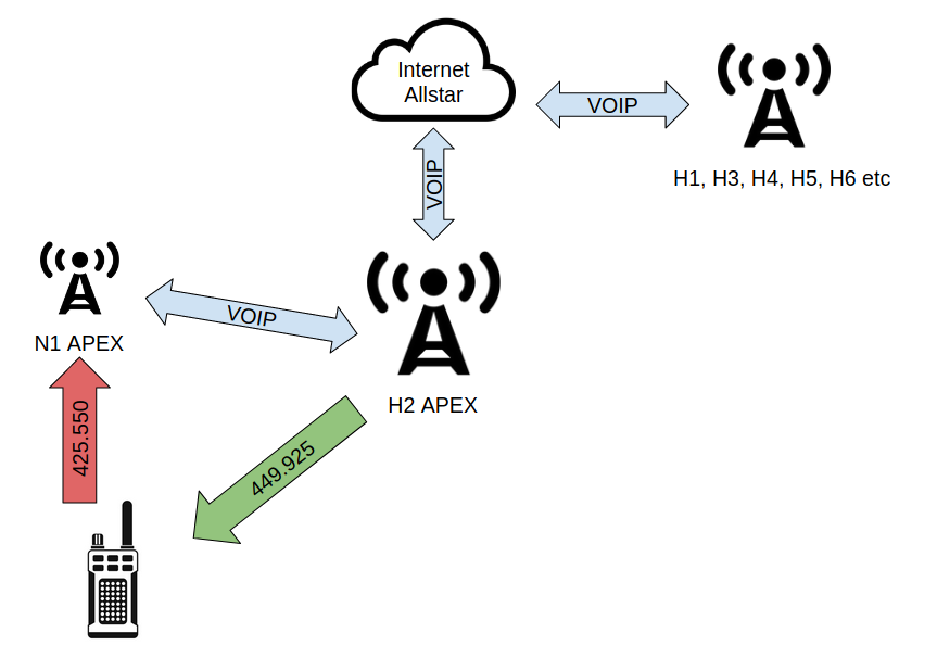
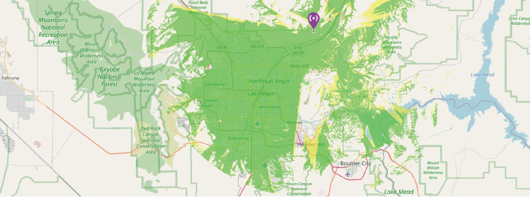
Angel Peak (8881′) Provides an input to H2: 449.850 MHz (-) (Receiver Tone for H2 Access: 156.7) Receives on: 425.550 MHz Tone: 156.7
Just to make this a bit more clear, N1 is a receiver, not a repeater. It provides a secondary input path to the H2 repeater. The receiver listens on a frequency that is almost 20 MHz below the normal input frequency of 444.850 for H2. The intent is to allow the H2 repeater to receive an input signal that is outside of the EPLRS (Enhanced Position Location Reporting System) interference range that is sometimes is directly interfering with the H2 input on 444.850 MHz.
Background
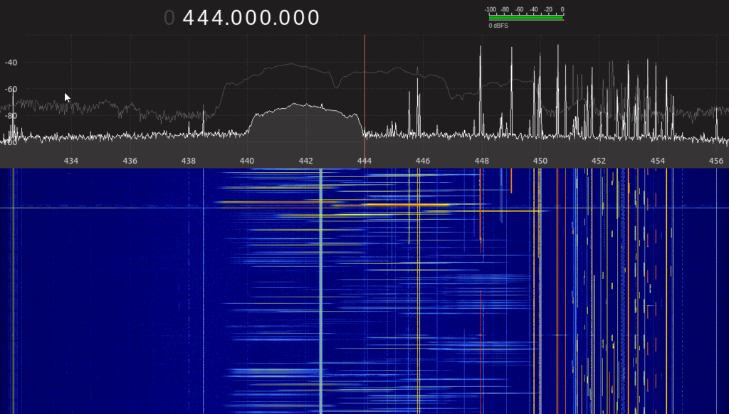
If you listen to the W7HEN network, you will often hear what is referred to as “popcorn”. This is interference from the EPLRS system. It’s worth noting that we are secondary users of the 420-450 MHz allocation, so this is just something that we need to put up with. While the EPLR system is suppose to be able to operate over anywhere of the 420-450 MHz band, it appears to be configured to mostly hop between ~439 MHz and ~449 MHz segment. Attached here is a screenshot of an EPLRS emission showing 30 MHz of bandwidth from a SDR in real-time when the EPLRS was really active.
Lorem ipsum dolor sit amet, consectetur adipiscing elit. Ut elit tellus, luctus nec ullamcorper mattis, pulvinar dapibus leo.
In the upper plot, there is a light grey line, which is a “peak hold” showing the frequency response of all the hops. The lower plot, called a waterfall shows the hops over time, with the color gradient being the intensity. The waterfall shows only a few seconds of time, and it’s clear to see how the H2 input (444.925 MHz) gets clobbered by several overlapping hops.
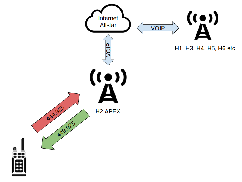
The attached image [h2_standard_operation.png] shows the standard operation of using H2 as a repeater with a 444.925 MHz input and a 449.925 MHz output.
The attached image [h2_standard_operation.png] shows the standard operation of using H2 as a repeater with a 444.925 MHz input and a 449.925 MHz output.
If you would like to try it, program a channel in your radio with the following configuration:
You should be aware, some radios will not allow you to transmit FM below 430 MHz. If a MARS/CAP modification is possible on your radio, it may allow it to transmit in this lower part of the 70cm band, your milage may vary.
Deployment
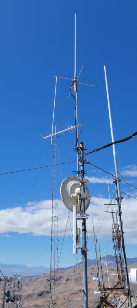
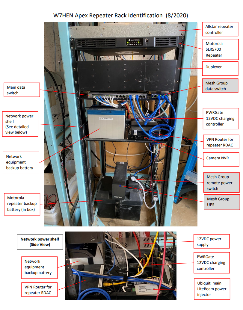
After a couple weeks of testing/modifications/tuning of the N1 node, we were able to deploy it up to Apex Peak in March 2021. Followqing is a picture of the 6-element yagi that is currently being used for N1. It is set in a horizontal polarization, thus far in testing, it has performed well.


