TEK NET
The Henderson Amateur Radio Club is pleased to present our Tek Net every Sunday evening, starting at 8pm local time (0300 UTC).
The audio portion of the Tek Net will be found on the Henderson Amateur Radio Club Repeater Network (RF). The audio may also be accessed via Echolink (W7HEN-R node 740644) and Allstar (node 44045).
The audio will refer to this page, so that the listener can more fully understand the concepts as they are presented.
All are welcome!
May 28, 2023
‘Soldering refresher by building a digital 24 hour clock kit’
I did a bit of looking for the right type of components, usability, ease to assemble and costs for tonight’s presentation.
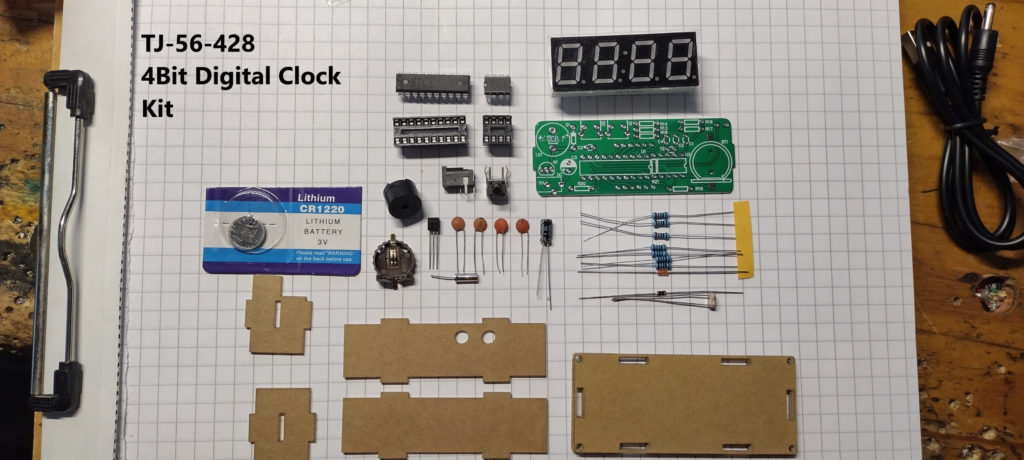
The kit is the MIOYOOW TJ-56-428 4Bit Digital Electronic Clock Kit. (cost $15.95)
The clock has several mode settings and displays hours and minutes, ambient temperature, alarm, date and has a built-in battery back-up to maintain the correct time when power to the device has failed.
Includes a clear plexi-glass pre-machined enclosure with hardware screws/nuts, and USB power cord.
This kit was delivered in 3 days from Amazon.
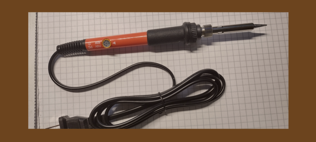
The DGMQKJ Soldering Iron 60 Watt, Temperature controlled Iron will be a excellent addition to your station tools at less then $10.00. It came with a 1/16″ wide chisel tip, which is perfect for today’s soldering project
This iron arrived in 3 days also.
What is soldering?
Soldering is the process of combining two base metals ( component lead & circuit board pad or hole) via a filler solder metal with a lower melting point.
In this process, the base metals (components) being joined are heated to the soldering temperature but do not
become liquid, only the solder liquefies.
Types of solder available for circuit board soldering.
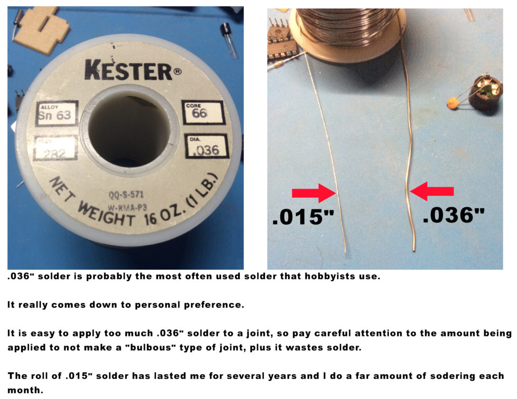
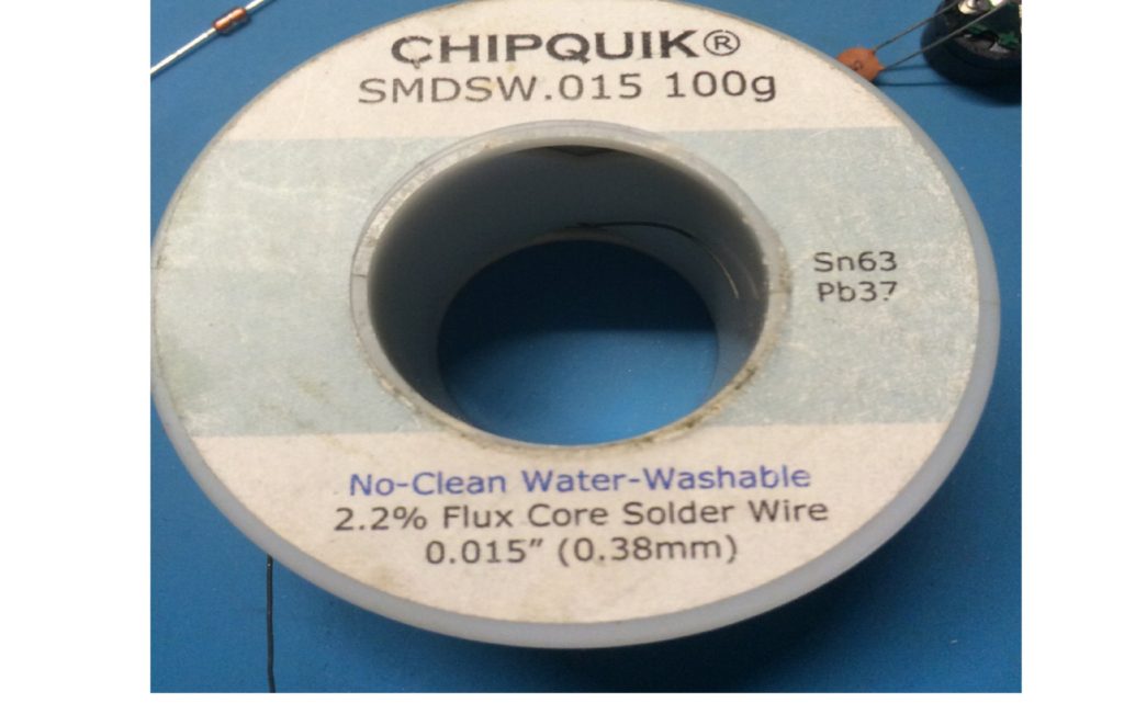
This .015″ solder is my favorite to use when building boards with small component leads.
It has a quality flux and is small enough to provide a good solder flow into the hole and around the component lead without adding too much solder to the joint.
Each of my solder joints uses about 1/4″ amount of this size solder.
I do a lot of soldering and this roll has lasted me for several years with a lot more available.
Refresher Soldering tips summary…
Safety first, when soldering make sure that the room is well ventilated because of the fumes from soldering with a flux core solder should be avoided.
Wear eye protection because soldering can have small amounts of solder to splatter at times.
Make sure that the iron is carefully placed out of the way when in the standby condition.
Irons of the 15W to 30W range are good for most electronics/printed circuit board work.
Anything higher in wattage and you risk damaging either the component or the circuit board.
Turn on the soldering iron and set temperature above the melting point of your solder. 600°- 650°F (316°- 343°C) is a good place to start for lead-based solder and 650°- 700°F (343°- 371°C) for lead-free solder.
Irons of the 15W to 30W range are good for most electronics/printed circuit board work.
Before each solder joint, clean the tip and pre-tin the tip with a small amount of solder.
The small amount of solder from wetting the tip will help to transfer the heat quickly to the pad and component lead.
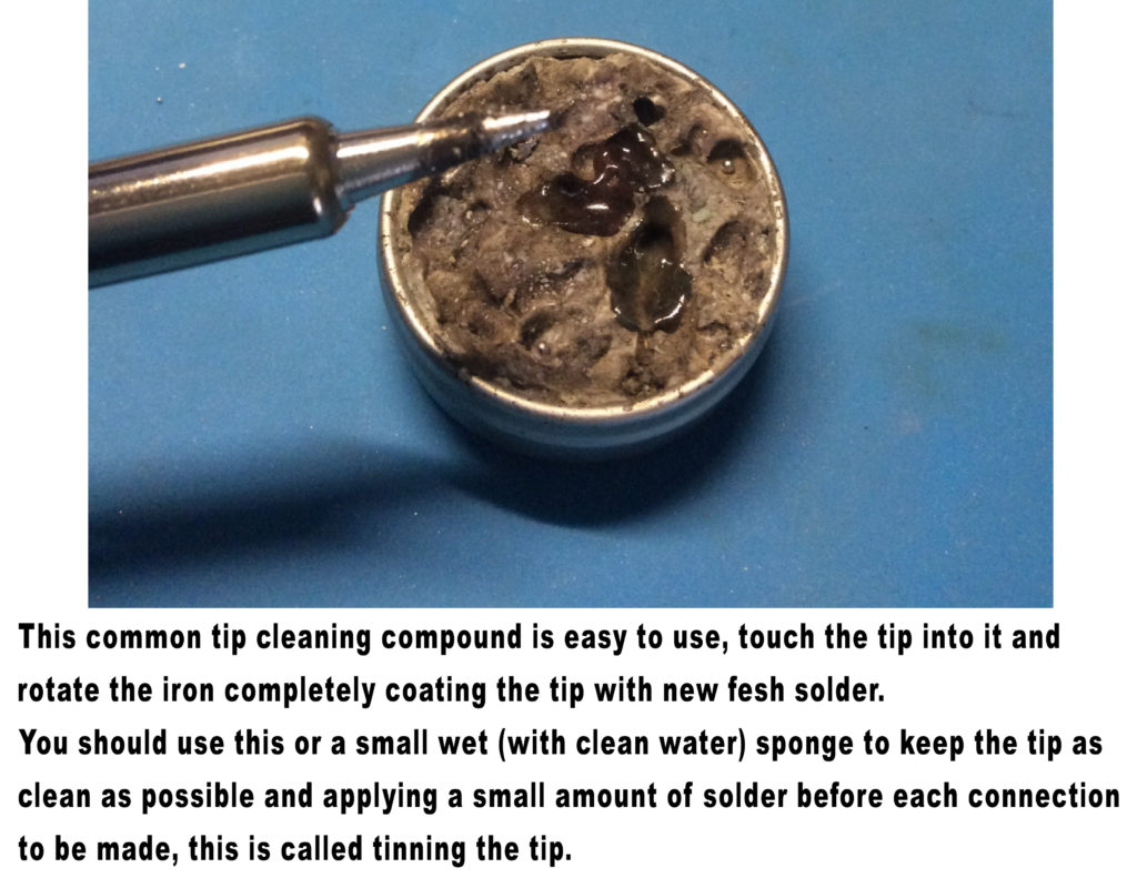
NOTE…After soldering a joint and your returning the iron to it’s holder/rest area, I always swipe the tip on the wet sponge to remove any burned rosin flux from sticking to the tip.
This condition if left on will eat into the tip silver plating, causing areas to no longer accept solder due to the plating being gone.
OK…let’s start building.
Read thru the installation directions completely before starting assembly.
The complete manual download is at the end of the is page.
As seen from the picture of the kit above, there isn’t a lot of parts involved keeping the project easy, short and sweet.
Lay out all the parts before starting to make sure you have all components listed in the instructions sheet.
And that you understand each parts description.
On a circuit board like this, that has the part descriptor printed on the board, if you can’t find a part’s location, keep looking (like the crystal Y2) it’s there, closely printed between two capacitors and the side of the 8-pin socket.
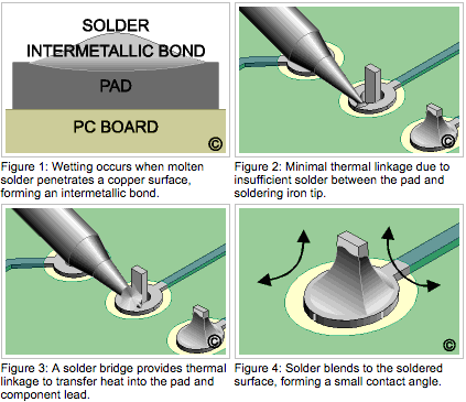
In the picture to the left, the top right image should be showing the flat side of the chisel tip against the lead and touching the pad, then apply the solder from the back side of the lead allowing the solder to flow into the hole and around the lead.
Your finished joint should look pretty close to the image in figure 4.
If your joint looks fat and doesn’t have nice taper up the lead, your probably applying too much solder. (that’s why I use the thinner .015″ solder)
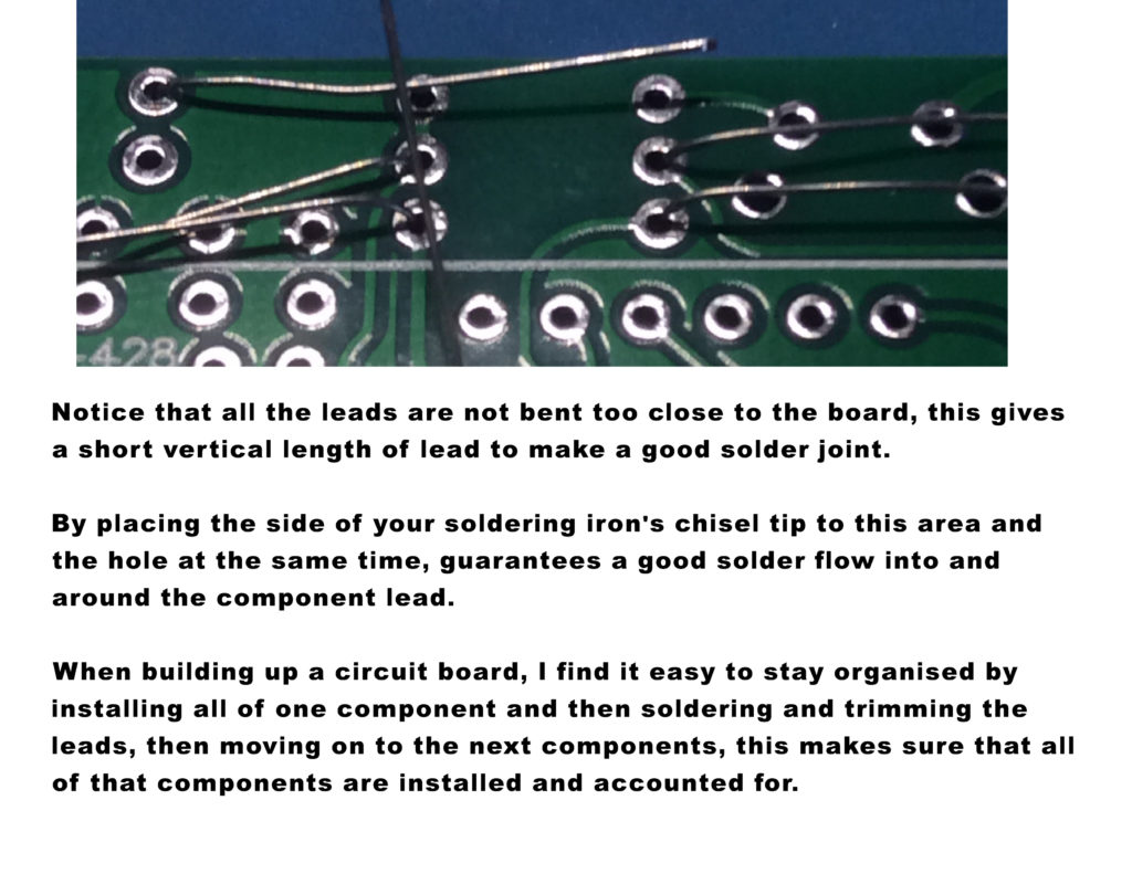

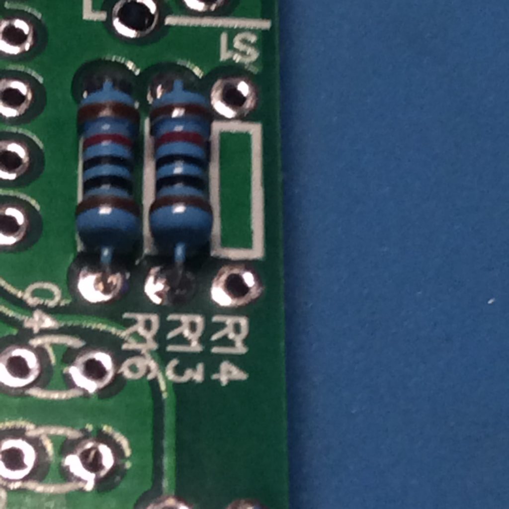
As can be seen above, the solder has flowed thru the hole and has made a good connection on both sides of the board.
I have found that using the smaller solder and applying it to the hole allows it to flow so nicely. The temperature of my iron is normally set to about 600 degrees F.
As seen below, when placing the parts on the board, make sure that they are flat and all the way inserted before soldering the component.
You can tell if the socket isn’t flush because the pins will have different lengths sticking thru the board.
As seen below, make sure that the IC socket is flush with the board.
I usually solder one pin of the IC socket (normally one on the end) then turn it over and check to make sure that it is still in the correct position, if it moved while soldering, with your finger holding the socket down, reheat the solder on the one pin of the socket and it should seat down nicely.
At that point, if the rest of the pins for that socket are sticking thru the board evenly, you can solder the rest of the pins.
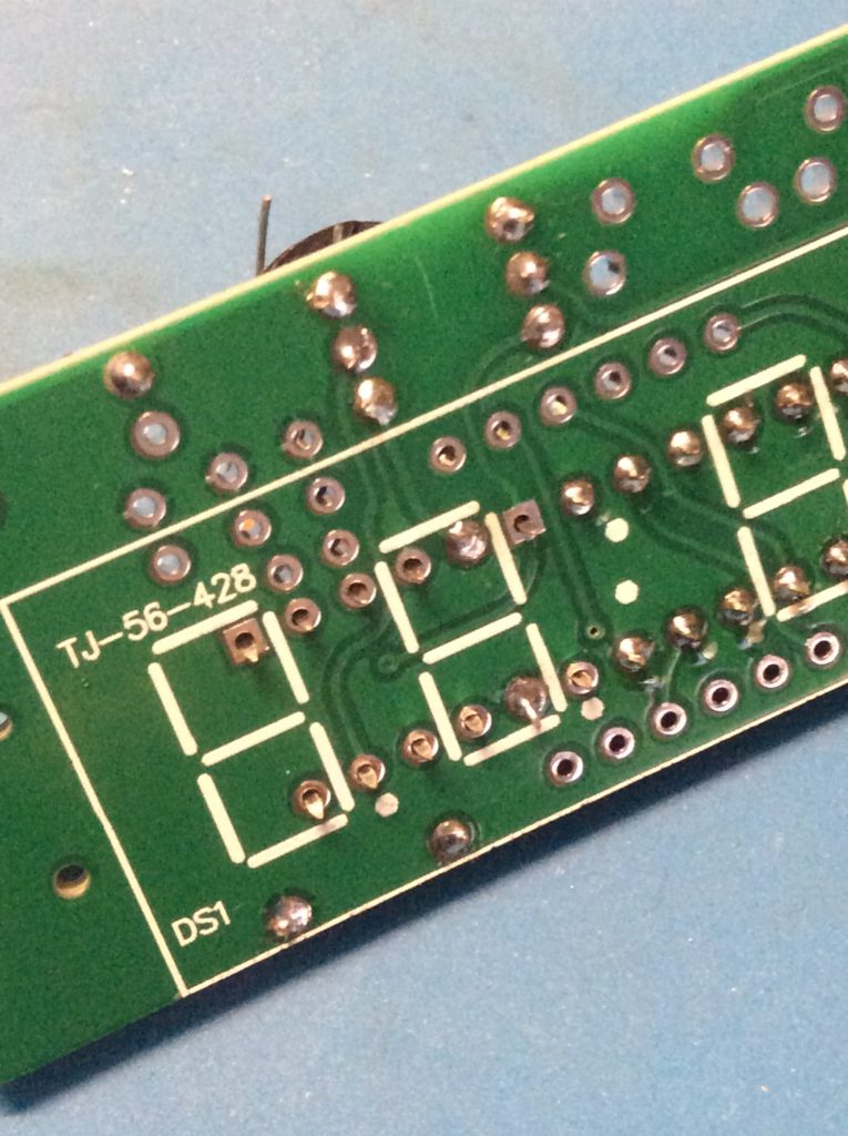
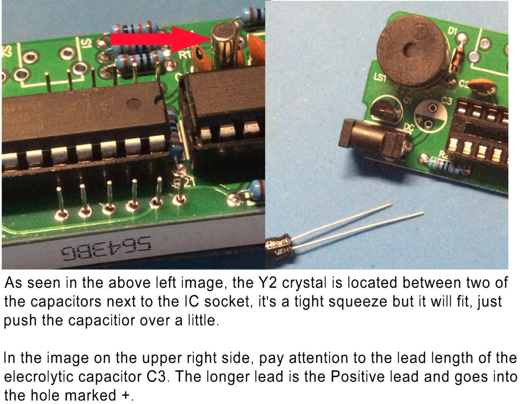
When looking for a part that doesn’t seem to be printed on the board with all the rest of the parts, look on the back of the board, like R15.
You can also peel the plastic film off of the LED display if desired.
When installing the LED display make sure that you install it with the decimal points on the display matching the white dots on the circuit board.
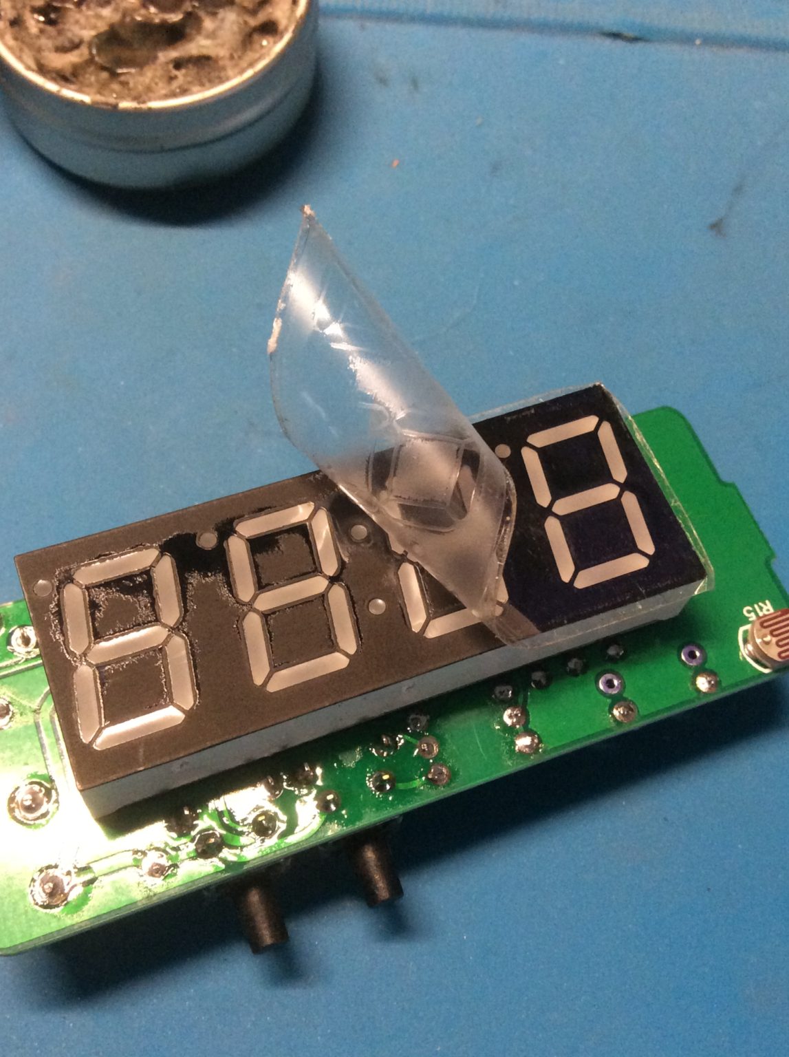
After you have finished all the soldering, as you attempt to hold the pieces of the plexi enclosure pieces together…good luck.
My fingers were not as nimble as they use to be, the pieces did put up a good fight.
However in the end…I did prevail!
I found that using some scotch tape to hold the pieces in place until the entire enclosure was together and ready for the screws, did the job nicely.
One last thing…
Can you damage a circuit board with a soldering iron?
YES, While you need to make sure your soldering iron is hot enough to melt the solder, you want to avoid overheating your solder at all costs. This can cause severe damage to your PCB, the other components and even your soldering iron tip.
That about rounds things up for today’s project.
The complete assembly manual and clock setting instructions is downloadable here.Digital_clock_manual
Read thru the instructions carefully.
It took me several tries to get the settings correctly set by pausing too long between button clicks, but finally got it the way I wanted.
If you should have any problems or issues with your kit or soldering, send me a text or email and i will attempt to help solve the problem.
Having a battery back-up to the clock’s settings is handy, if you have to remove power or there is a a power failure, when it gets powered up it is displaying the proper information.
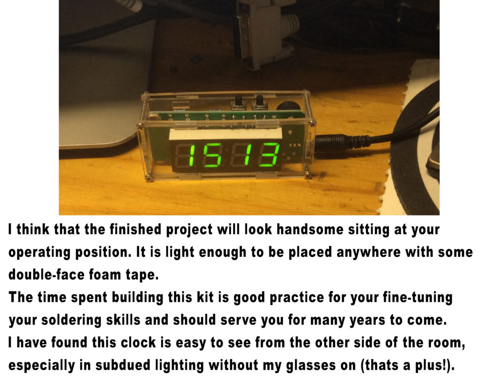
This is a great little 24 hour LED clock sitting on your desk or out in your vehicle.
