TEK NET
The Henderson Amateur Radio Club is pleased to present our Tek Net every Sunday evening, starting at 8pm local time (0300 UTC).
The audio portion of the Tek Net will be found on the Henderson Amateur Radio Club Repeater Network (RF). The audio may also be accessed via Echolink (W7HEN-R node 740644) and Allstar (node 44045).
The audio will refer to this page, so that the listener can more fully understand the concepts as they are presented.
All are welcome!
August 13, 2023
“Communications Service Monitors, what they do and how to use them.”
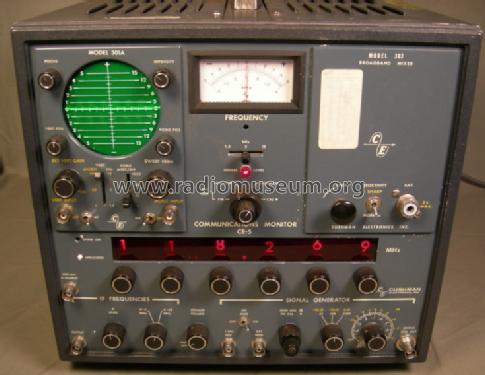
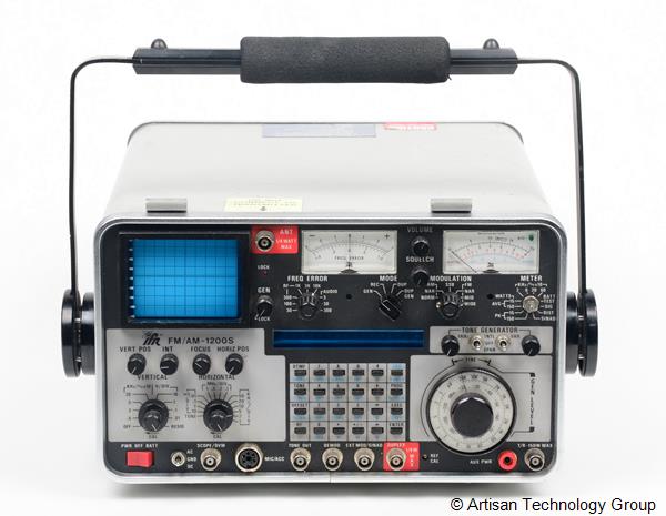
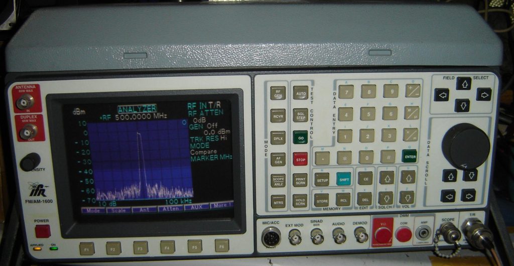
Below are some of the different monitors over a 25 year period.
But what is a “service monitor” as we have heard folks on the repeaters talk about them.
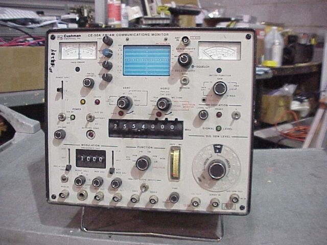
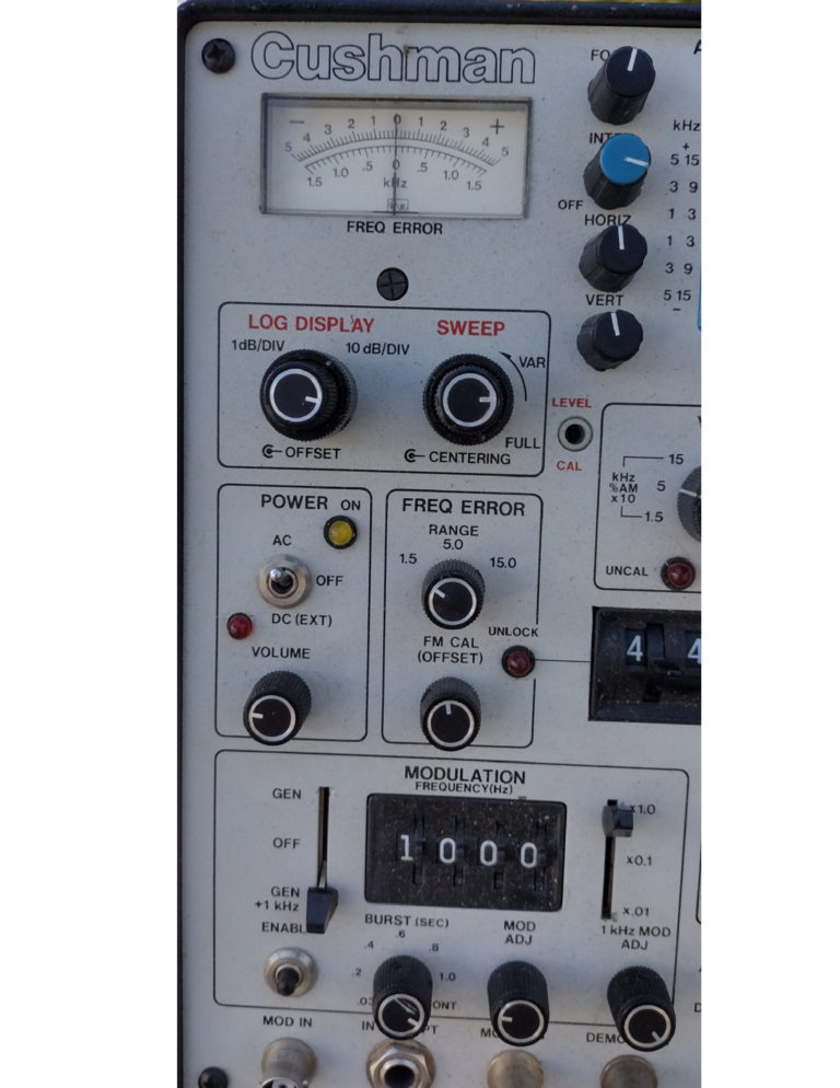
I will be concentrating on the CUSHMAN CE-5110 (the White face unit) pictured below and to the left. This unit cost between $17,000.00 and $22,000.00 depending on options it came with.
This is my personal unit and prefer it to the newer menu driven units for its speed of operation and its service life (they were built like tanks!).
A service monitor is a combination of several pieces of precision test equipment all wrapped up into one package.
In the 70’s, 80’s and 90’s a service monitor was an absolute must have in any two-way radio shop because most of the radios still had crystals that had to be set on frequency, thus the SM ( service monitor) had to have a precision oven controlled master oscillator for its reference frequency.
This allowed the technician to key the transmitter into a dummy load and with the SM in the “Receive” mode be able to read the frequency as well as see the waveform of the transmitter.
Maximum Deviation was measured and adjusted while talking into the transmitter’s microphone if needed. While keying the transmitter and not speaking into the microphone the technician could now see the waveform being created by the CTCSS tone generator and adjust the tone level accordingly inside the radio being measured.
As seen below the SM had different sections that could be operated in conjunction with other sections.
You can see to the left, the meter is calibrated to display the received transmit signal FREQ ERROR at either 1.5Khz , 5Khz, 15Khz.
Freq Error is set to the 1.5 Khz setting you are able to see how far off frequency the transmitter is in 100 hz increments.
When the needle is in the center or “0” than the transmitter is dead on frequency.
This section is for measuring the transmitter’s frequency based on the frequency that has been dialed up in the middle section of the SM.
The modulation section is a synthesized audio generator that will be injected on to the generated signal.
Modulation can be injected in several ways (Continuous, burst, etc) as well as varying the tone level.
The number 1 Red arrow is where the external antenna is connected to the RF input section of the SM.
You must use care when connecting on to this BNC input, the high sensitivity of the monitor can be damaged.
This input is used for making “Over-the-air” measurements such as frequency error or deviation measurement from the repeater without making a trip to the repeater site.
Number 2 Red arrow is where you would set the display to show received deviation either 1.5Khz, 5Khz, 15Khz
(if you have low transmit audio here is where it is really going to show up)
Red arrow number 3 is the the variable signal generator output control knob.
A good operating radio’s receiver should be pretty much quieting with a signal of .3Uv to .5Uv.
