TEK NET
The Henderson Amateur Radio Club is pleased to present our Tek Net every Sunday evening, starting at 8pm local time (0300 UTC).
The audio portion of the Tek Net will be found on the Henderson Amateur Radio Club Repeater Network (RF). The audio may also be accessed via Echolink (W7HEN-R node 740644) and Allstar (node 44045).
The audio will refer to this page, so that the listener can more fully understand the concepts as they are presented.
All are welcome!
July 23, 2023
“Filters, different types and how they are used in Ham radio”
The subject of filters is extremely broad and I’m not able to cover all the aspects of filters.
I am going to cover the different types of filters by name and how they are used in Ham radio in RF, Audio and power supply environments.
Some of the more common names we hear talked about are:
HIGH-PASS
LOW-PASS
BAND-PASS
BAND REJECT
NOTCH FILTERS
These can be made up from Cavity filters, RC & LC filter circuits as well as SMD filter types.
High-pass and Low-pass circuits are in every two-way radio made.
These circuits are in the transmitter frequency stages as well as in the receiver sections.
Where we used to have large coils and capacitors in a transmitter, now days we will see SMD devices providing the same functions but in a smaller foot print on the circuit board.
RF Low-Pass filter
A Low-pass filter (LPF) is a circuit that only passes signals below its cutoff frequency while attenuating all signals above the cut-off frequency.
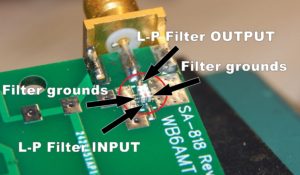
Shown below is a SMD RF Low-pass filter on the antenna output of a NiceRF.com’s SA818 radio module.
It’s purpose here is to pass the main frequency F1 transmit frequency and greatly attenuate (or not-pass) any harmonic frequencies above the selected cut-off frequencies such as F2 (900 mhz component) down by about -60 db from leaving the antenna and possibly causing interference to nearby receivers or transmitters.
This particular LP-filter is made by Mini-Circuits and can handle 6 watts of RF on the input.
Audio Low-pass filter
In an audio environment a low-pass filter is also known to be called a High-cut filter. This type of filter is used to remove high-frequency sound from and audio signal.
Its called a low-pass because it allows low frequencies (like voice audio)to pass through a stage of the circuit, while reducing in amplitude higher frequency signals like the high-frequency hiss that occurs between each stage of the circuit. This is a normal occurance due to the stage gain of each stage of the circuit.
Just like the Low-pass filters in RF the audio Low-pass filter has a cut-off range also.

Here is a circuit that would be used in an audio signal path to eliminate the 60hertz component (AC hum) that could be on an audio line.
This is a passive circuit.
Active circuits using high gain operational amplifiers (Op-amps) allows the designer a wider range of control than from a passive filter circuit.
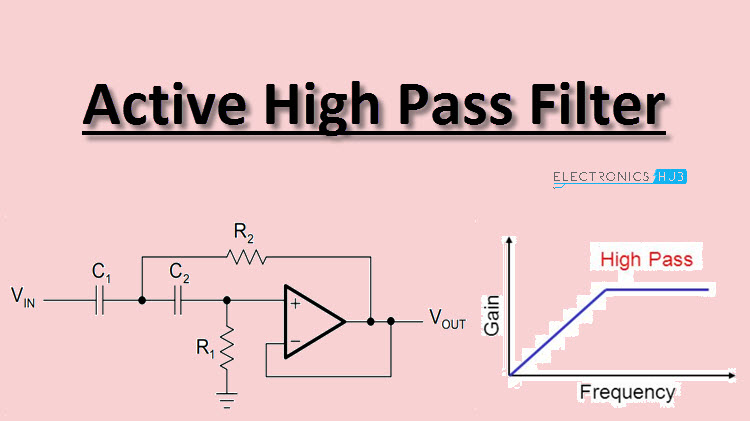
An active low-pass filter would be used often as a tone control of an audio amp circuit or can be frequency adjustable like the roofing filters in your HF radio.
RF High-Pass Filters (a complement of a Low-Pass filter)
The most common use for High-pass filters in RF is when you want to take advantage of the natural occurring harmonic signals from an oscillator circuit or a “multiplication stage”.
An example of this would be when the High-pass circuit is after a frequency generating circuit (example.. 12Mhz main crystal oscillator ) and the circuit is tuned to the harmonic frequency desired, say 36Mhz is wanted, the 3rd harmonic is normally pretty strong and can be used in this manor to multiply in stages up to any frequency desired as the output of a transmitter, including microwave frequencies.
Normally a buffer or driver circuit is used after the High-pass circuit to bring the new frequency level up to the needed signal to drive the next stage.
Band-pass / Band-Reject filters
Any ham that used a radio thru a repeater most likely was able to do that thanks to the Duplexer on that repeater system.
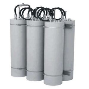
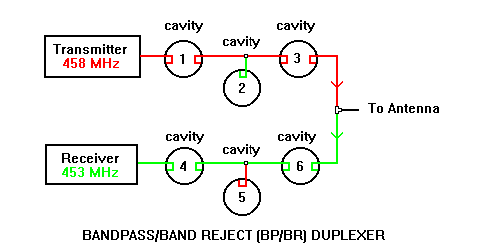
On the left is a typical duplexer arrangement. From the size of the cavities shown, this is a VHF duplexer. For ham use the cavities will be tuned to provide maximum isolation at approximately 600Khz on the tuned frequency. As shown on the right is a 6 cavity UHF 5Mhz wide duplexer.
In the diagram above cavities #1 & #3 would be tune to the transmitter’s frequency (band-pass), while cavity #2 is tuned as a notch filter on the receiver’s frequency, thus attenuating or dumping RF energy on the receivers input frequency from the transmitters signal.
Cavities #4 & #6 are band-pass cavities tuned to the receiver’s center frequency, passing all signals on the receiver’s input without any attenuation, but with the help of cavity #5, any transmit RF energy is being dumped or “Notched” out of the signal path.
This is how we can use one antenna on both the repeater’s transmitter and receiver at the same time without damaging the receiver’s front-end.
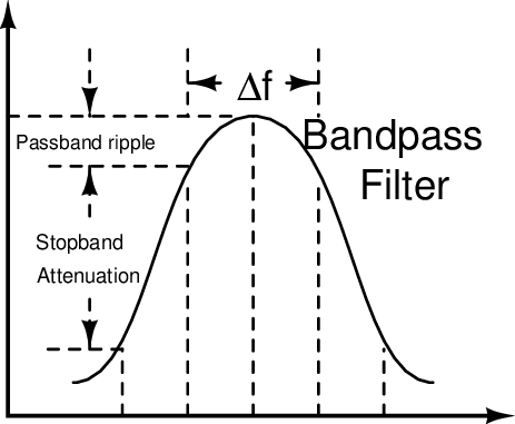
The stopband attenuation is what makes this all possible.
There are cavities used in some duplexers that have a Notch Loop built in to each cavity, allowing for a 6 cavity band-pass duplexer with the Notch loops on each cavity creating a much deeper notch of the transmitters energy from reaching the receiver input.
Low-pass filters in power supplies
With more power supplies being used to power our radios that are using switching protocals there are low-pass filters being used to keep the high frequency component from the switching oscillator being on the DC line out.
We can also see in the schematics of some switching power supplies have added the use of a 60Hz LPF to get rid of that annoying AC hum that some equipment is sensitive to even at low levels.

