TEK NET
The Henderson Amateur Radio Club is pleased to present our Tek Net every Sunday evening, starting at 8pm local time (0300 UTC).
The audio portion of the Tek Net will be found on the Henderson Amateur Radio Club Repeater Network (RF). The audio may also be accessed via Echolink (W7HEN-R node 740644) and Allstar (node 44045).
The audio will refer to this page, so that the listener can more fully understand the concepts as they are presented.
All are welcome!
May 7, 2023
‘Radio Direction Finding using the Doppler system technique’
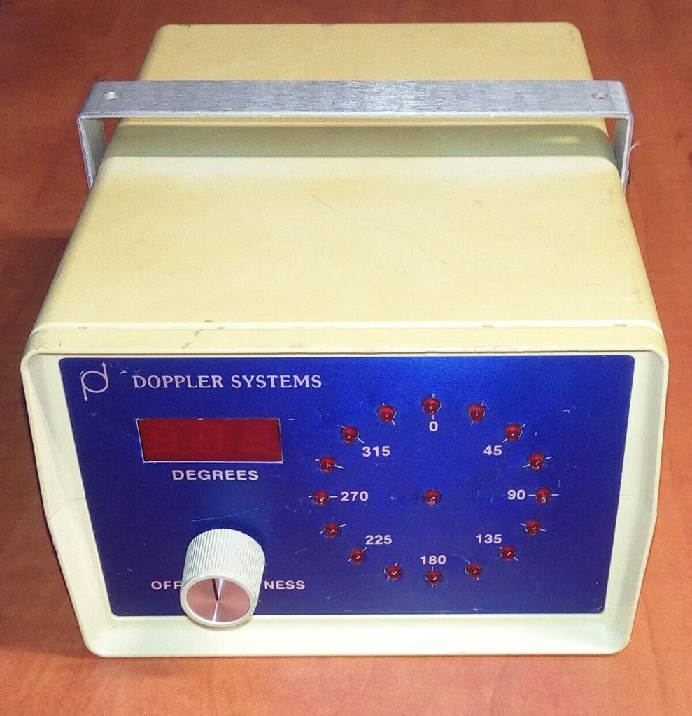
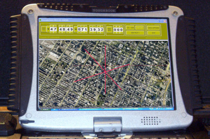
Tonight, I will break down how a doppler antenna system works and displays to the user the direction the signal is coming from.
What is Doppler, anyway?
Back in 1842 Christian Doppler discovered that the frequencies increase as two objects move toward each other, however they decrease as they move away.
You can hear this effect when listening to a train horn as it approaches and then passes you.
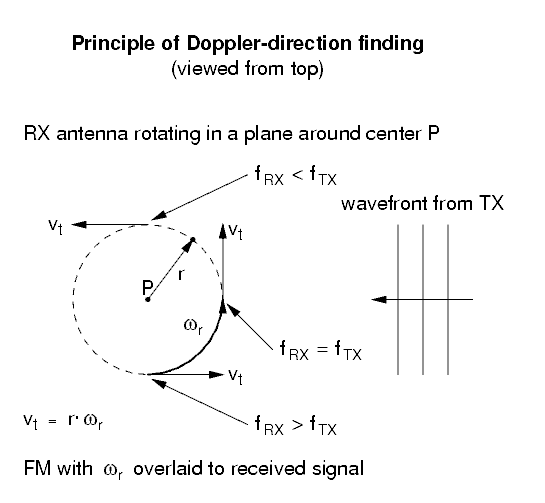
A rotating antenna achieves the motion of one object relative to the another in the radio frequency spectrum.
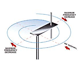
As a result, the received signal FM modulates at the frequency of the antenna rotation.
Applying the modulated RF signal to the input of a narrowband FM receiver produces a tone at the audio output of the receiver at the antenna rotation frequency (speed).
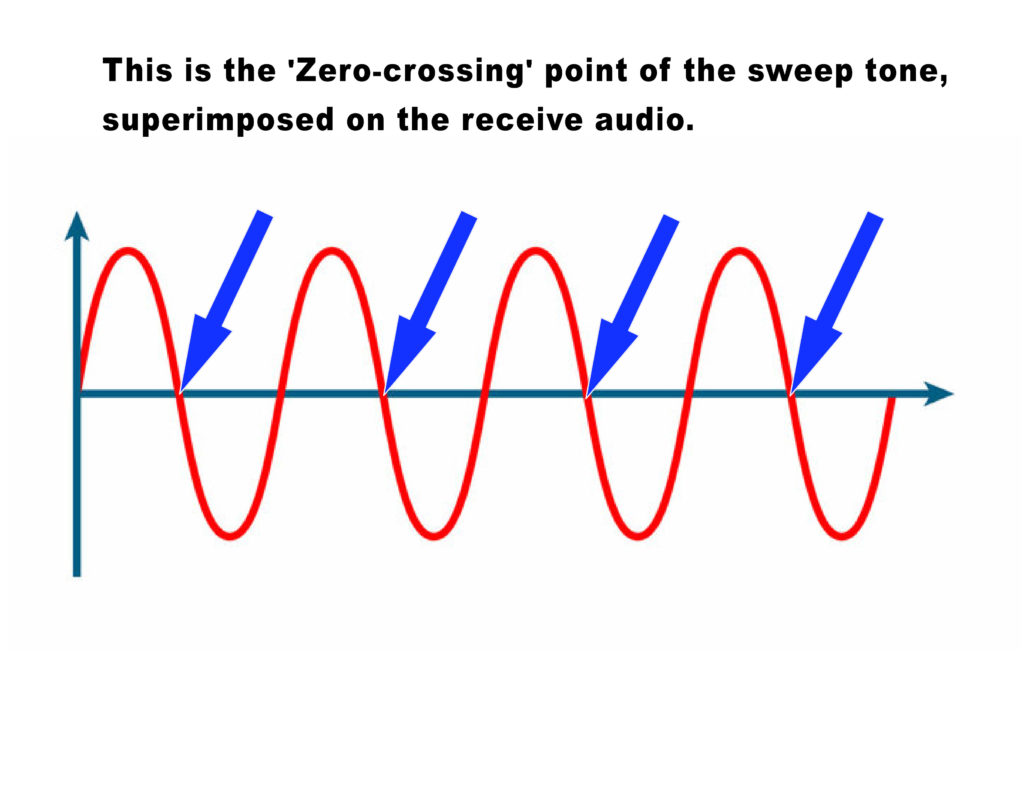
This is called the commutation or sweep frequency. This tone is super imposed onto the receiver’s normal audio output.
The phase of the tone relative to the clock reference used to rotate the antenna is the bearing angle, as seen below.
It was found that the rotational rate of the antenna had to rotate at 20,000 RPM or greater for it to work.
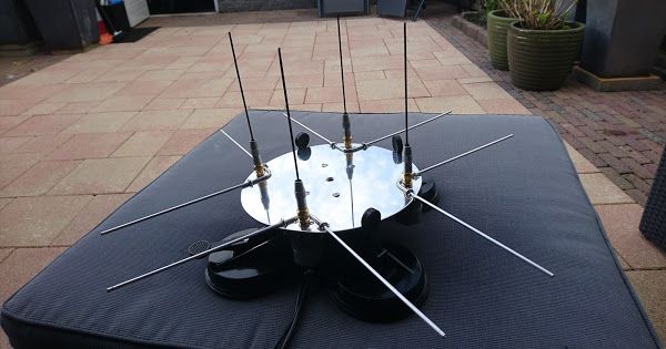
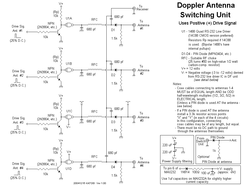
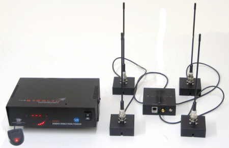
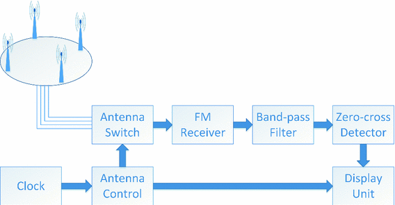
Clearly not a practical feat, instead several antennas (usually 4, 8 or 16) are arranged in a circle and electronically rotated. This is accomplished by connecting and disconnecting the antennas one at a time at 600 to 1000 Hz.
As each antenna is connected/disconnected this creates a tone heard on the output.
This tone is analyzed and and calculated as to which antenna was closest to the signal at the moment of the “zero-crossing point” of the tone’s sine-wave and displayed by illuminating the LED representing the direction of the signal.
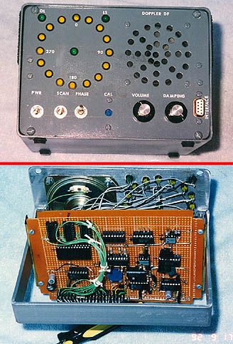
My first Doppler antenna was home built in 1975 from three circuit boards that came from a ham in Los Angeles. The original prototype is seen below.
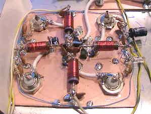
The boards consisted of a 8 antenna switch board, audio processor board and the 16 LED display board. The audio was connected to the external speaker of the 2-meter radio allowing the phase of the audio signal to be analyzed.
My early 8 antenna board was mounted to a old STOP sign that was found on the side of the road, each antenna was mounted at each of the corners of the sign. Perfectly spaced, Excellent!
The early Doppler units used 8 antennas and very effective, allowing the user with a portable radio to walk around the vehicle and the LEDs would follow in real time.
