Tek Net
February 26, 2023
"Building a 300 watt dummy load"
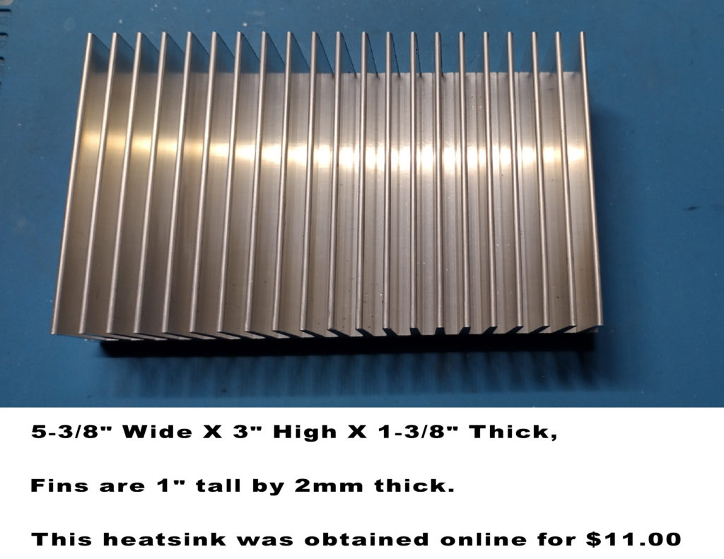
This is a great 1 hour weekend project. The materials needed are (1) RF resistor, (1) heatsink, (1) coax pigtail with connector to match your transmitter or coax switch.
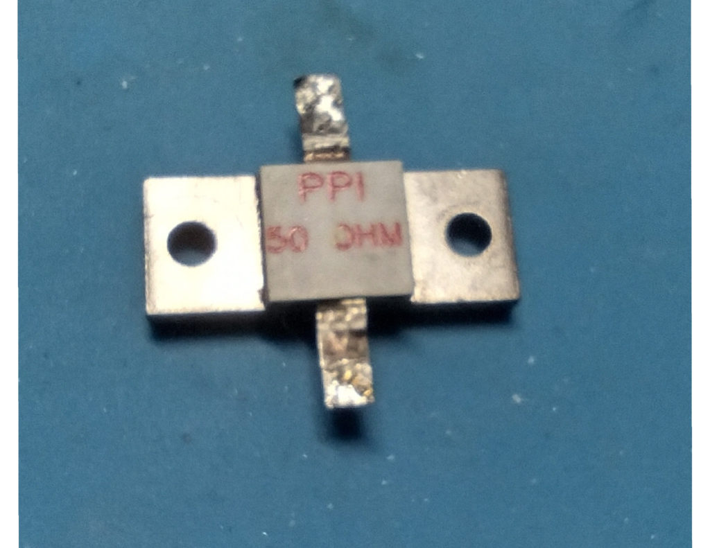
This weeks Tek Net project is centered around using a high power 300 watt RF resistor by PPI.
This little guy cost $23.00 for the 300 watt resistor and as little as $14.00 for a 150 watt version.
This resistor was a pull out from a damaged high power RF combiner.
The resistor was used as a 50 ohm termination point on the combiner’s circuit board.
They are available from several sources online.

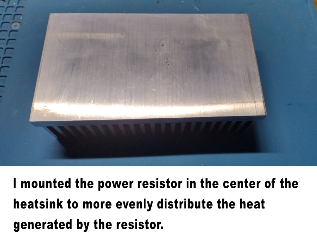
When drilling the first mounting hole, I found it easier to drill from the fin side of the heatsink for the first 1/8″ mounting hole. That way my holes were centered between the fins.
Making sure that the resistor is squared to the edge, I drilled the second hole from the resistor side, to ensure that the hole was correctly located.
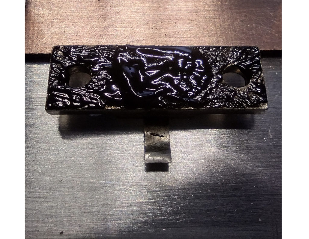
Before you attach the resistor, use some thermal compound or thermal paste so that the resistor transfers the heat more efficiently to the heat sink. Both surfaces should be free of any foreign material and completely smooth.
Depending on the brand or manufacturer of the compound, it may be white, grey or black in color.
The thermal compound fills in any microscopic gaps between the flat surfaces, to maximize heat transfer from the resistor to the heat spreader (Heatsink).
Using blank 1/16″ PC board material, cut two pieces approximately 1-3/8″ x 3/4″, which will serve to be the mounting surface for the shield of the coax cable and the center conductor of the coax.
Be sure to use a fine wire brush or steel wool to clean and polish the copper surfaces to be soldered.
An additional piece cut to 1/4″ by 3/8″ will serve to be the connection tab for the center conductor of the coax and the mounting tab from the resistor. This is held in place with a drop of super glue. Once soldered it won’t move.
The piece of circuit board material on the opposite side will be the ground connection to the coaxs shield.
Only one rivet is needed to securely hold the boards in place and not be in the way of the shield to copper solder connections.
Using a drop of super glue to hold the copper circuit board in place, drill a 1/8′ hole for a pop rivet to secure the boards from the fin side.
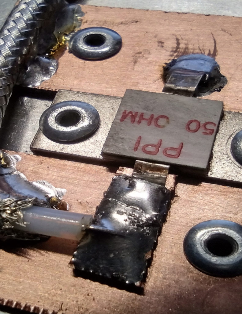
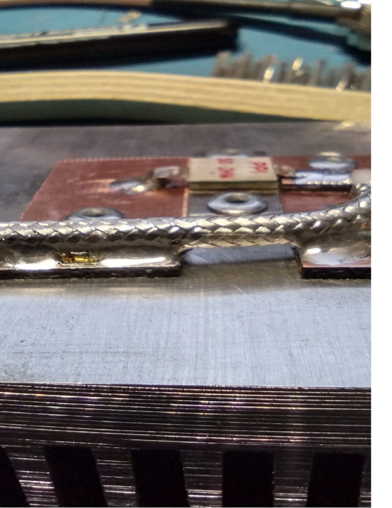
The coax I used here is RG-142B, it is high temperature Teflon, double shielded silver braid coax with a solid center conductor.
Using a razor blade or sharp knife slice 2″ of outer jacket from the coax, careful not to cut too deep and nick the silver conductors of the shield.
Trim back the shield 3/8″ from the end.
Remove 1/8″ of the Teflon center insulator, exposing 1/8″ of the solid center conductor.
I found it easier to shape the bend prior to soldering the center conductor first.
Then holding the shield down tight to the board with something that won’t melt (the end of a wooden wire brush), apply a liberal amount of solder at several locations, connecting the braid to the pc board material.
Don’t worry about melting the insulator material, the Teflon can take the heat without any damage.
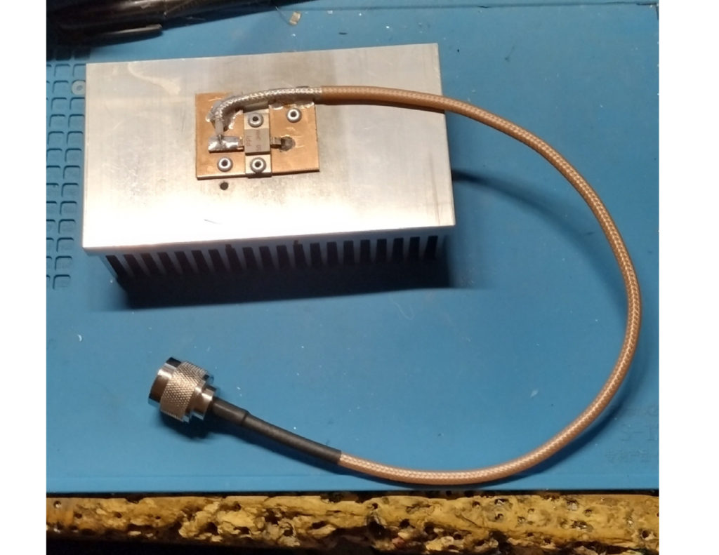
Here is the completed dummy load, if desired you can also attach a cable clamp to protect the cable from creating a weak point where it is soldered to the pc board material.
I’m thinking that I will add a small project box covering the resistor and circuit board material to prevent anything from touching the dummy load and then the fins will be facing up as the dummy load will sit on the project box.
