TEK NET
The Henderson Amateur Radio Club is pleased to present our Tek Net every Sunday evening, starting at 8pm local time (0300 UTC).
The audio portion of the Tek Net will be found on the Henderson Amateur Radio Club Repeater Network (RF). The audio may also be accessed via Echolink (W7HEN-R node 740644) and Allstar (node 44045).
The audio will refer to this page, so that the listener can more fully understand the concepts as they are presented.
All are welcome!
January 8, 2023
” Differences between Linear and Switch Mode Power Supplies”
Power supplies…this is the one item found in almost every ham’s radio setup or operating position.
The power supply is is needed to provide the DC voltage and current necessary for the radio transceivers to operate correctly and at the rated power level of the transmitter.
Power supplies are needed to charge the battery back-up that many folks have to power their radio equipment in the case of a main power failure to the house.
Linear type VS Switched Mode Power Supplies
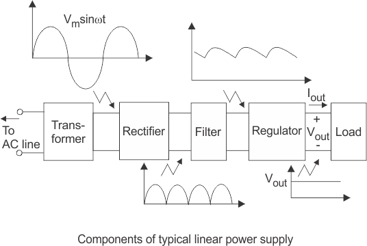
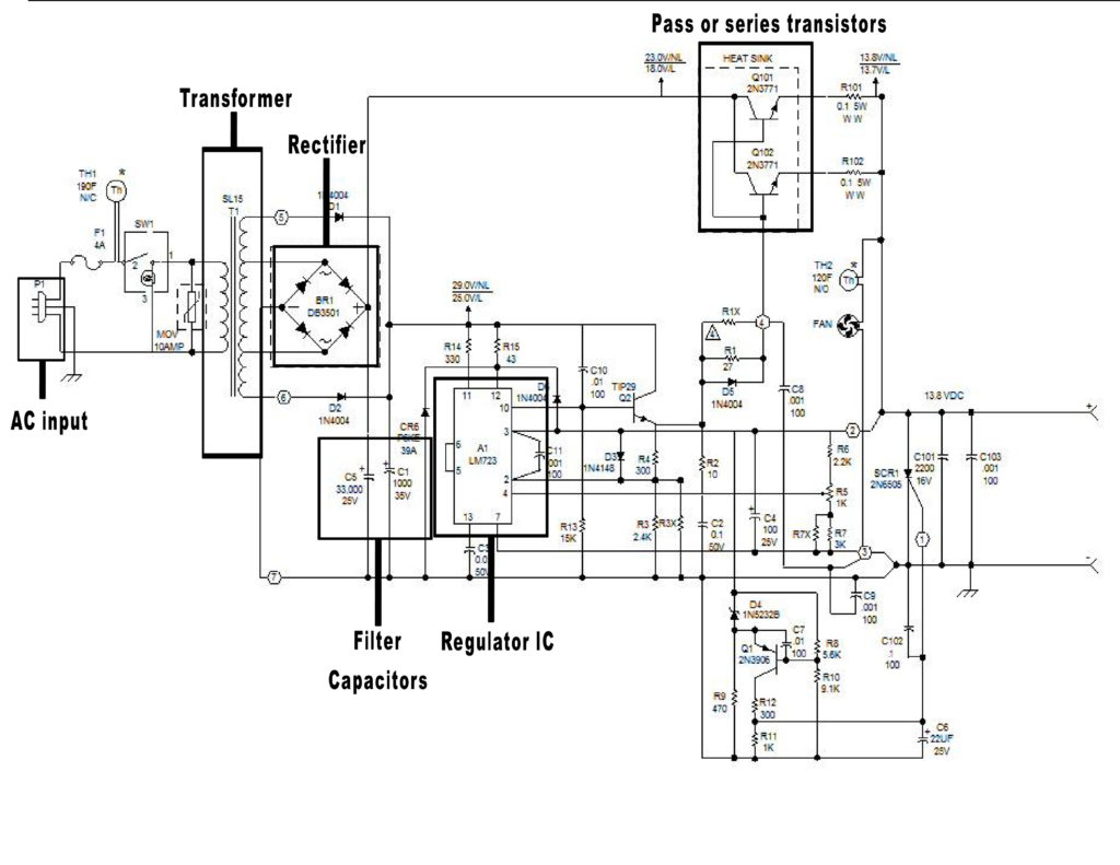
To the right is the schematic of a linear supply, it gets its name from the Linear devices that are used to regulate the output of the power supply. The linear transistors are also called series or pass transistors or regulators.
The transformer is the part that reduces the AC voltage and determines the current capabilities based on the Secondary winding wire size and number of turns around the iron core or frame of the transformer.
The output of the transformer feeds the Rectifier section, which is normally 4 diodes or a full-wave Bridge rectifier.
After the rectifier section is the filter/ smoothing section, consisting of inductors and filter electrolytic capacitors.
The last section is the regulator section consisting of high-current transistors that are controlled by a regulator circuit. The pass transistors are designed to pass the higher current needed to operate the transmitters power amplifiers or meet the current demands of the station’s equipment.
A note here about transformers….
The iron-core transformers used in linear power supplies are very heavy due to their construction design.
The transformer for this Astron RS-20 weighs in at a little under 18 pounds, in comparison to the Astron SS-30 switching supply that comes in at 4.3 pounds and uses a Ferrite core transformer.
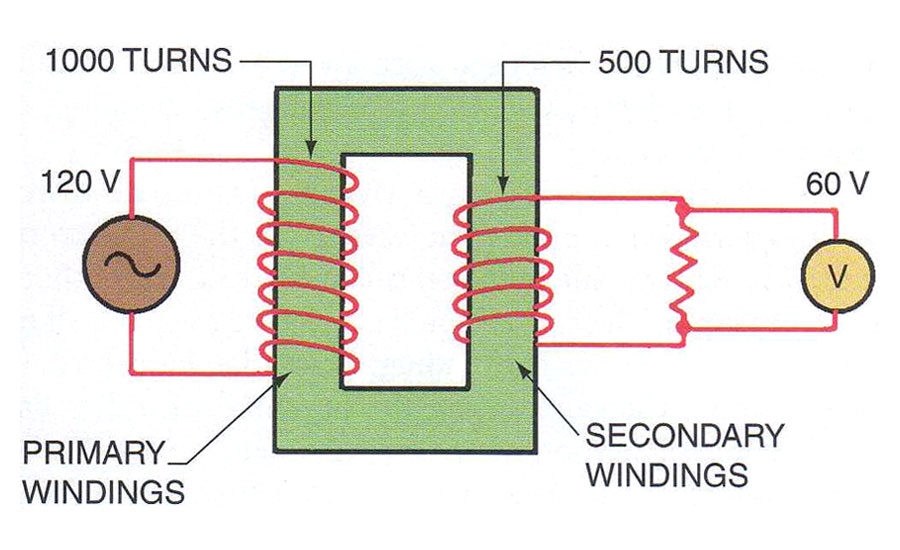
You can see in the image above that there is a definite relationship between the number of wire turns on the primary and the secondary, the number of secondary windings is how the output voltage is determined.
The size of the secondary winding is what determines the current availability at the output of the supply.
Although the linear power supply is generally not as efficient as a switch-mode power supply (SMPS), they do afford better performance, lower cost and simpler circuit design.
If you scrutinize the electronics landscape, you will see the widespread use of linear power supplies in applications that require strict noise mitigation.
Linear power supplies can’t boost the output voltage as easily as a SMPS type power supply.
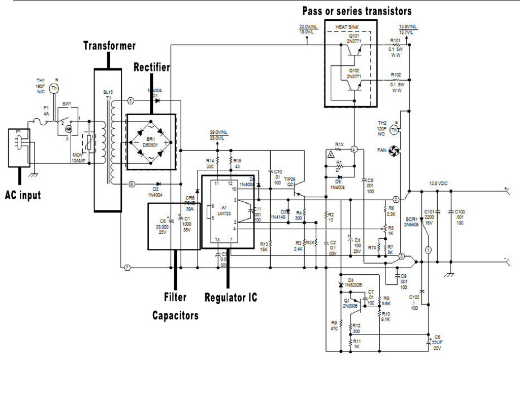
Below is the schematic of an Astron RS-20 linear power supply.
You can clearly see each of the sections as described above.
The additional components are are over voltage safety and short circuit crow-bar protection devices.
An SMPS or switcher differs from a linear power supply in how it converts the primary AC voltage into the output DC voltage. The SMPS utilizes a power MOS-FET transistor to produce a high-frequency voltage that passes through a small transformer, and then filters it to remove the AC noise.
However, a linear power supply delivers DC by distributing the principal AC voltage through a transformer before filtering it to remove the AC noise.
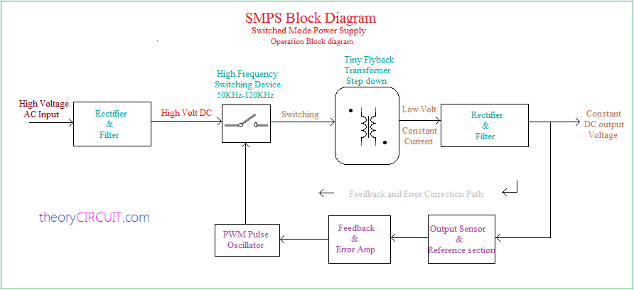
As you can see the AC coming into the power supply is first rectified and then filtered before it is applied to the switching (chopper circuit) modulation section.
Using Pulse Width Modulation at a higher frequency (50-120Khz) than the 60 Hz AC input before the Ferrite step down transformer you don’t need as large of a transformer for the same amount of current as in a Linear power supply.
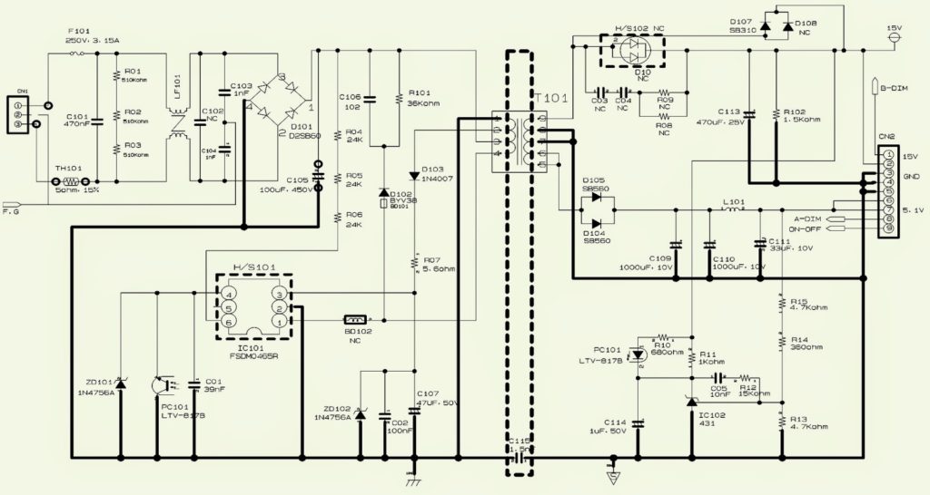
The above schematic is one of a massive number of schematics available to show a switched type supply.
The reasons for the different schematics is that the switch mode supply can easily provide a multiple number of outputs at different current ranges by the addition of more PWM sections.
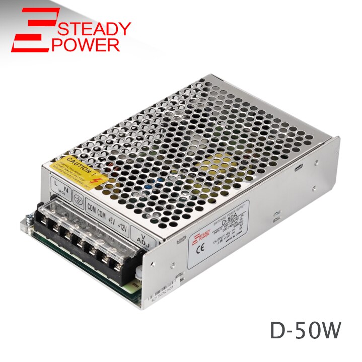
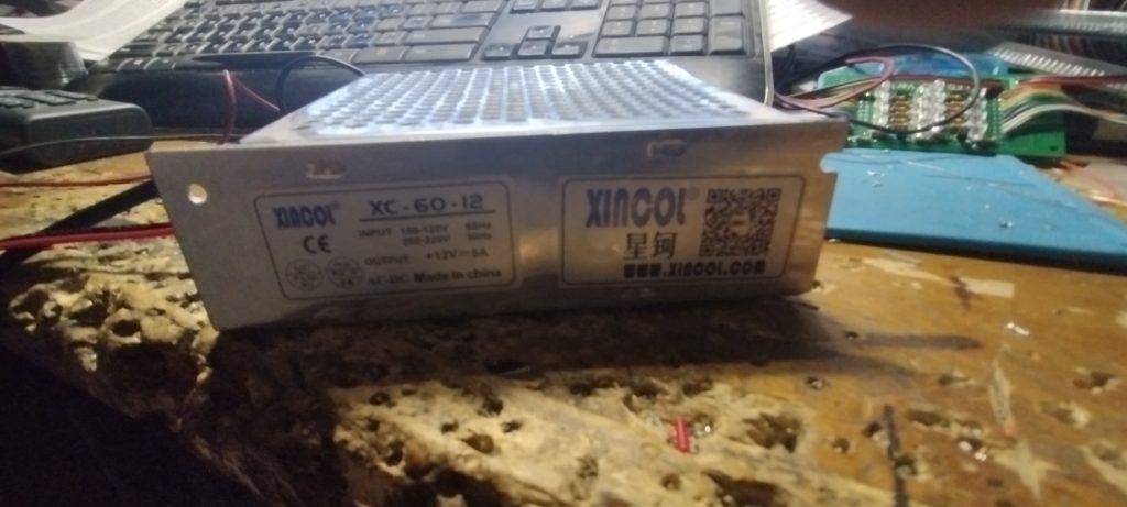
To the left is a multiple DC output power supply providing regulated +12 volts @2 Amps and also Regulated +5 volts @ 6 Amps.
Size is 3-1/2″ W by 1-3/8″ H by 6″ Deep.
Weight 1-3/4 pounds.
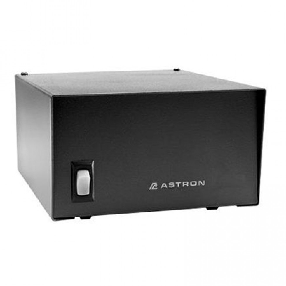
This 5 Amp 13.5 volt Astron power supply is 3-1/2″ H x 6-1/8″ W x 7-1/4″ D and weighs in at 7 lbs.
