TEK NET

The Henderson Amateur Radio Club is pleased to present our Tek Net every Sunday evening, starting at 8pm local time (0300 UTC).

The audio portion of the Tek Net will be found on the Henderson Amateur Radio Club Repeater Network (RF).  The audio may also be accessed via Echolink (W7HEN-R node 740644) and Allstar (node 44045).

The audio will refer to this page, so that the listener can more fully understand the concepts as they are presented.

All are welcome!

“The PL259 – What it is and how to use it”

By Tony Dinkel WB6MIE

This Tek Net was originally done by Tony WB6MIE 2 years and 9 months ago, in that period of time we have many new members who may benefit from Tony’s presentation.

He is busy dealing with personal matters right now but is here in spirit i’m sure.

The PL259 UHF Connector

In amateur radio, we deal with Radio Frequencies. Because of that, we also have to deal with ways to get RF from place to place in the most efficient way possible.

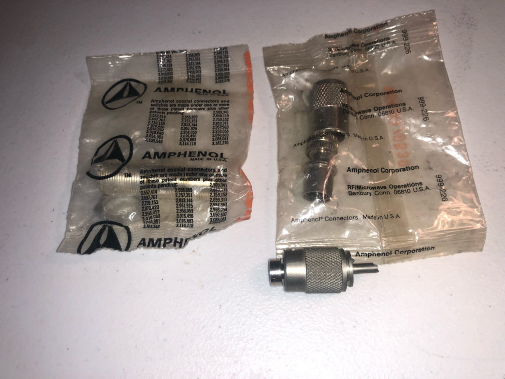
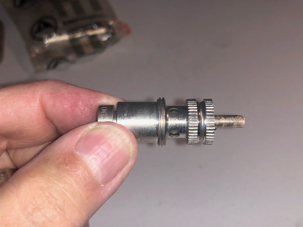
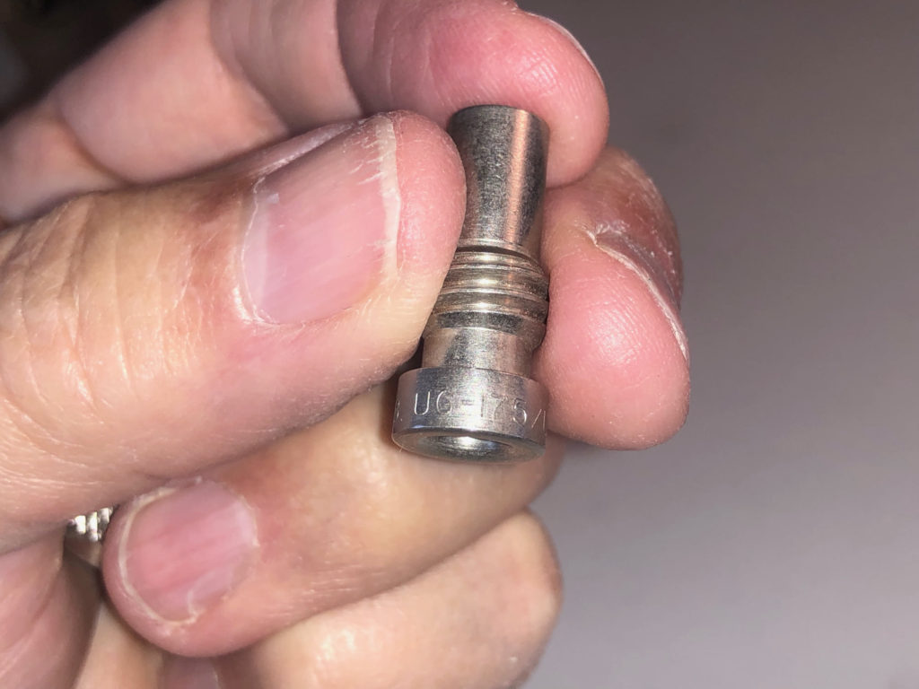
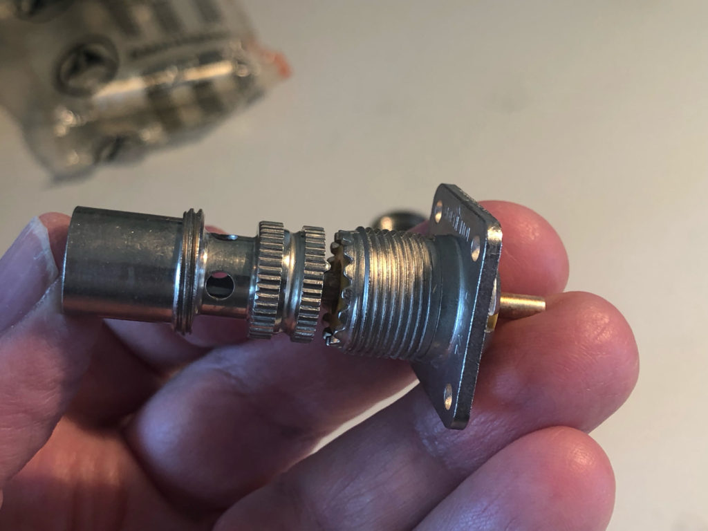
That means we need to deal with RF cables, transmission lines, and connectors. We need to understand the application of RF connectors to get our signals out of one box and into another, or outside of our shacks, into our backyards, and into our antennas.

The oldest and most popular of these connectors is most likely the PL-259 male or UHF connector. Some reference sources call this a “shielded” banana jack connector.

It sure doesn’t look like a banana plug to me, it is a coaxial connector and does not have the characteristic spring-loaded pins that are indicative of banana jack connectors.

It is also referred to as a UHF connector. That’s because back in the 1930s, when this connector was designed, UHF started at 30mhz.

Today, the UHF frequency range starts at 300mhz and continues to 3000mhz. This is moderately amusing because this connector’s performance starts to degrade at about 400mhz, making it less than desirable for use at UHF frequencies. This is because it has about a 35-ohm impedance bump at the pin to socket interface.

This really isn’t a very good connector for anything above two meters. Better constant impedance connectors exist, such as type N and BNC. The ins and outs of putting these types of connectors on cables will be discussed in coming months.

The dielectric materials used in these connectors are not consistent at all. Here on my bench I have several samples of PL-259 connectors and each one has a different dielectric.

One has Teflon®, one has polyethylene plastic and another uses what looks like a phenolic resin type material. Although this really doesn’t bother us in ham radio applications, in high-performance RF systems it does matter. Teflon has pretty much become the standard dielectric material in my corner of the radio frequency universe.

Here’s a view down the barrel of a typical PL-259 connector. Without the threaded UG-175 adapter it can accept RG-8 or RG-213, but that’s another show. Tonight I will be talking about attaching one to smaller cable, RG-58.

Note that the female receptacle connector has little teeth around its threaded perimeter.

If you look closely at the mating surface of the main connector body you can see one of two tabs that should evenly be engaged in two of the valleys between the teeth on the female connector.

This locks the male plug in position from spinning as the shell is tightened.

I also feel the need to explain that there is no such thing as a PL-259 female connector. The designation for the receptacle of a PL-259 male connector is SO-239, as seen below.

Assembly of a PL-259 male connector is very simple and straightforward. I’m using an RG-58 type cable for this example.

A UG-175 threaded adapter is required for RG-58 size cable.

The cable braid then folds back along the adapter body and this then threads into the connector body.

The adapter threads inside the main connector body.

The cable center conductor passes through the pin to be soldered


The center conductor of the coax needs to be soldered to the center pin of the connector. Use the solder sparingly, try to get it in the center pin, not on the outside of the pin.

If solder gets on the outside of the pin, remove it with a file or sand paper, so as to not deform or damage the receptacle for the pin.

When soldering on this connector be aware of the dielectric on your PL-259 so that you don’t use too much heat and melt it and now loosening the pin to the dielectric.

I do not solder the braid through the 4 holes on the connector body. The heat required is just too much for the thermoplastic used in the RG58 to survive. If you would like to try it, be my guest.

But don’t say I didn’t warn you!

The only thing left to do at this point is to thread the outer shell on to the connector and tighten it on to the radio or antenna SO-239 receptacle.


There is a multitude of videos online  and always someone on the repeater network that can asnswer your questions if you are experiencing a problem, or contact me at < wb6amt@cox.net > and i will get back to you as soon as possible.

Next week is “ASK the PROS” night, so bring your questions or issues to the net, so that they can be resolved.


73 and Happy Hamming…

DE WB6AMT Earl