TEK NET
The Henderson Amateur Radio Club is pleased to present our Tek Net every Sunday evening, starting at 8pm local time (0300 UTC).
The audio portion of the Tek Net will be found on the Henderson Amateur Radio Club Repeater Network (RF). The audio may also be accessed via Echolink (W7HEN-R node 740644) and Allstar (node 44045).
The audio will refer to this page, so that the listener can more fully understand the concepts as they are presented.
All are welcome!
November 6, 2022
“Building a small UHF directional antenna”
With the clubs upcoming H2 repeater move to Angel Peak, I have heard some people discussing how they are going to be able to use the new repeater installation on Angel’s particularly if they live in the shadowed areas being blocked by some of the mountain ranges between the Las Vegas valley and Angel’s.
Tonight I will show you how to build a 8-9db gain directional qubicle quad antenna.
All the parts can be obtained from your local Home Depot or Lowe’s, except the coax and that is up to your choice.
RG58 is inexpensive and flexable, the example here was made with RG142B double shielded silver conductor coax because I was intending on using it on the transmitter hunts and I didn’t want any signal leakage thru the coax.
As shown here the antenna is about 15 inches long and 7 inches wide.
The orange fiber glass spreaders are cut from two 4ft long residential driveway markers, these fiber glass rods are 5/16″ in dia.
The boom is made from a standard length of Fir 3/4″ x 1-1/2″ x 24″.
You will need (4) 9-3/8″ rods and six 8-3/8″ rods.
When drilling the holes in the boom material along one side, be careful when you start drilling the next set of mounting holes on the other side so that they don’t interfere with each rod in the other direction.
This copper wire was in the area where the parts for hanging picture frames is located.
At the time I made these antennas the package of 25′ of 18Ga wire was around $6.00.
I cut five pieces of wire 28″ long prior to threading the wire thru the spreaders.
Preparing one end of the wire is easy.
Using an 1/8″ drill bit to form the loop on the end, wind one loop around the drill bit and then back onto the wire a couple of turns to give you a nicely formed eyelet that will be used to connect the opposite end of the wire when it has been threaded thru all four ends of the spreaders and pulled tight.
When you start to thread the wire thru the spreaders, pull the loop up tight to the first hole and as you go to the next hole, keep the wire as tight as possible. When you get back to the loop, pull it thru the loop tight and wind it around itself 1 or 2 times then solder the connection.
When you are sanding the ends of the rods flat, keep in mind to make sure that they both ends are sanded the same way, or threading the copper wire will be difficult.
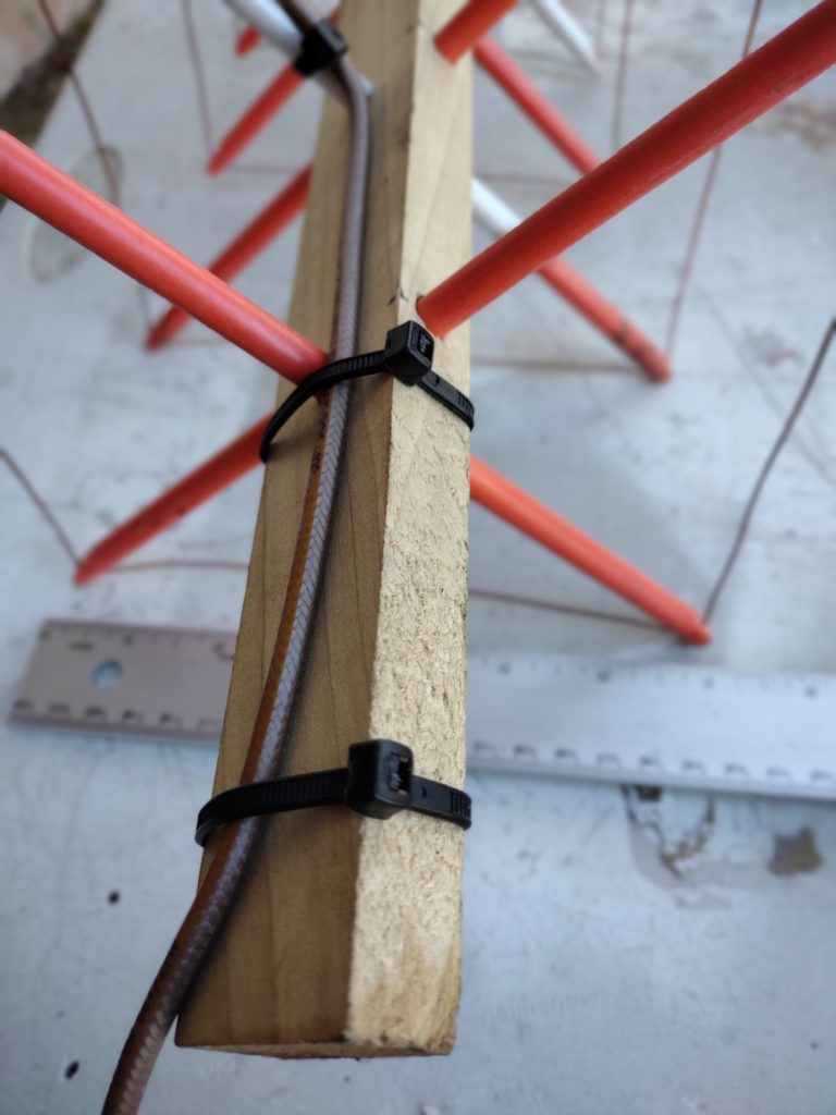
When preparing the Driven Element, sand down about 1″ so that you have enough room for two 1/16″ holes spaced about 1/2″ apart for the wire ends to pass thru and be secured.
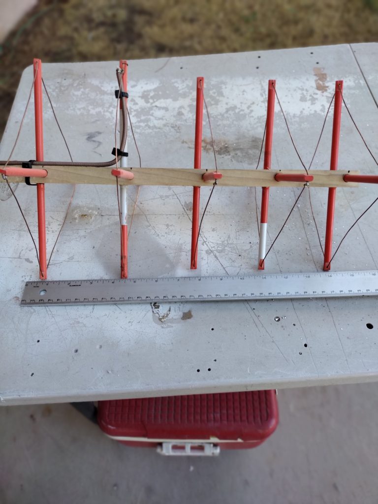
The Driven element is the only one where the wire is NOT connected to itself after being strung thru the rods.
After stringing the Driven elements wire, loop it around and tighten it and solder the connection so it won’t loosen.
Attach your coax ( shield and center conductor) to the ends as shown in the picture. The center conductor is connected to the backside connection of the Driven element.
To adjust the SWR on this antenna, after soldering the braid to one end of the loop, you can solder the center conductor to different locations on the opposite end of the wire element for your best SWR.
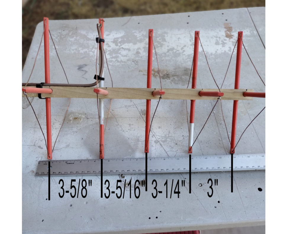
This is actually a full wave loop at this UHF frequency.
