TEK NET 20221009

The Henderson Amateur Radio Club is pleased to present our Tek Net every Sunday evening, starting at 8pm local time (0300 UTC).

The audio portion of the Tek Net will be found on the Henderson Amateur Radio Club Repeater Network (RF).  The audio may also be accessed via Echolink (W7HEN-R node 740644) and Allstar (node 44045).

The audio will refer to this page, so that the listener can more fully understand the concepts as they are presented.

All are welcome!

“How vacuum tubes work and do we still need them?”

As you can see from the image above, most tubes look the same, except the “Peanut” tube on the right hand end.

The Peanut tube was used in the first battery operated portable radios and walkie-talkies built for the military.

The wire leads were soldered to the circuit board instead of pins and sockets.

The batteries in these portables were normally “C” or “D” size cells for the filament voltages and a Burgess higher voltage battery typical 45, 67, 75 volts or higher for the B+ needed by the tubes. The size of these batteries dictated the actual size of the portable radio or walkie-talkies.

Battery types used in vacuum tube portable radios.

In the 1950’s when it became evident that transistors could be made to do the same job as the tube, but were considerably smaller, worked on much lower voltages, and were much cheaper to build in greater quantities due to the manufacturing production processes.

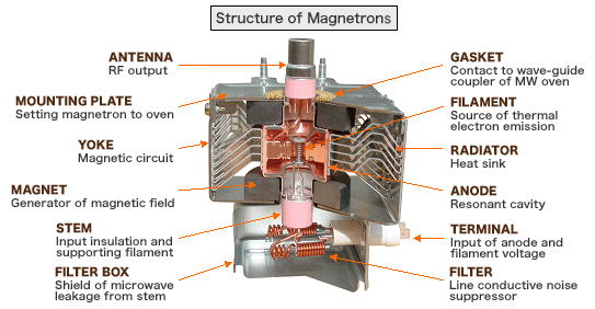
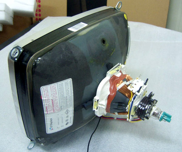
Although tubes lost their place in the storefront of consumer electronics, they still remain in significant use where there is need for a lot of power at very high (GHz range) frequencies, such as in radio and television broadcasting, industrial heating, microwave ovens, satellite communications, particle accelerators, radar, electromagnetic weapons plus a few applications requiring lower power levels and frequencies, such as radiation meters, X-ray machines and gieger counters.

How do vacuum Tubes Work?

Regular vacuum tubes work based on a phenomenon called thermionic emission, also known as the Edison effect. There is two types Direct and Non-direct.

When thermionic emission occurs in a vacuum tube, the wall with the heater is the cathode and is heated by a filament.

In most vacuum tubes the cylindrical cathode is heated by a filament (not too different from the one in a light bulb), causing the cathode to emit negative electrons that are attracted by a positively charged anode, causing an electric current to flow into the anode and out of the cathode (remember, current goes into the opposite direction than electrons).

First was the Diode….

consisting of the filament, the cathode and the anode.

Electric current flows through the filament in the middle, causing it to heat up, glow and emit thermal radiation – similar to a light bulb.

The heated filament heats the surrounding cylindrical cathode up, giving enough energy to the electrons to overcome the work function, causing a cloud of electrons called a space charge region, to form around the heated cathode. The positively charged anode attracts electrons from the space charge region causing a flow of electric current in the tube.

This is all happening in a vacuum, because air impedes electron flow. This is how a diode is used to rectify AC.

Then came the Triode…

In 1906 Lee de Forest discovered that adding a wire grid, called a control grid, between the anode and the cathode allows for the anode current to be controlled.

Triode’s construction is similar to the diode, with the grid being made from very fine mobyldenium wire. The control is achieved by biasing the grid with a voltage – the voltage usually being negative in respect to the cathode. The more the voltage is negative, the lower the current.

When the grid is negative it repels electrons, decreasing the anode current, if it is positive more anode current flows, at a cost of the grid becoming a tiny anode, causing grid current to form which might damage the tube.

Triodes and other regular tubes can be used as switches, amplifiers, a mixers and a lot of other uses to choose from.

Next were Tetrodes to the rescue!

Early triodes suffered from low gain and high parasitic capacitances.

In the 1920s it was found that putting a second (screen) grid between the first one and the anode, increased the gain and lowered parasitic capacitances.

This new tube was named tetrode, meaning in Greek four (tetra) way (ode, suffix).

The new tetrode wasn’t perfect, it suffered from negative resistance caused by secondary emission that could cause parasitic oscillations.

Secondary emission occurred when the second grid voltage was higher than the anode voltage, causing a decline in anode current with the electrons hitting the anode and knocking out other electrons and the electrons being attracted by the positive screen grid, causing possible damaging increase in grid current.

Finally Pentodes – the final frontier

Reducing secondary emission resulted in the invention of the pentode in 1926 by the Dutch engineers Bernhard D.H. Tellegen and Gilles Holst.

It was found that adding a third grid, called a suppressor grid, between the screen grid and the anode, removes the effects of secondary emission by repelling electrons knocked out of the anode back to the anode since it is either connected to ground or to the cathode.

Today pentodes are used in transmitters below 50MHz, as tetrodes in transmitters work good up to 500MHz and triodes up to the gigahertz range, not to mention audiophile use.

Common type of tube used today is a Magnetron…

The magnetron is similar to the diode, but with resonant cavities shaped into the tube’s anode and the whole tube located between two powerful magnets. When voltage is applied, the tube starts oscillation, the electrons passing the cavities on the anode, causing generation of radio frequency signals or energy, in a process similar to whistling.

X-ray Tubes

X-ray tubes are used to generate X-rays for medical or research purposes.

When a high enough voltage is applied to the vacuum tube diode X-rays are be emitted, the higher the voltage the shorter the wavelength.

To deal with heating of the anode, caused by electrons hitting it, the disc-shaped anode rotates, so the electrons hit different parts of the anode during its rotation, improving cooling.

CRT or Cathode-Ray Tube…

The CRT or the “Cathode-ray Tube” was the main display technology from the 1950’s to the 1970’s.

In a monochromatic CRT a hot cathode or a filament acting as a cathode emits electrons.

On their way to the anodes they pass through small hole in the control grid for the tube and helping to focus the electrons into a tight beam.

Later they are attracted and focused by several high voltage anodes. This part of the tube (cathode, control grid and the anodes) is called an electron gun.

After passing the anodes they pass the deflection plates and impact the fluorescent front of the tube, causing a bright spot to appear where the beam hits.

The deflection plates are used to scan the beam across the screen by attracting and repelling electrons in their direction, there are two pairs of them, one for the X-axis and one for the Y-axis.

Geiger–Müller tube…

Geiger–Müller tubes ( still my favorite!) are used in radiation meters, they consist of a metal cylinder (cathode) with a hole on one end and a copper wire in the middle (anode) inside a glass envelope filled with a special gas.

Whenever a particle passes through the hole and impacts the wall of the cathode for a brief moment the gas in the tube ionises, allowing current to flow.

This impulse can be heard on the meter’s speaker as a characteristic click!

Every once in a while I’ll hear someone say… oh, they don’t use or make vacuum tubes anymore!

Talk about being un-informed. Vacuum tubes are all around us, look in your ham shack…are you running a linear amplifier?

Chances are, that it has an 807, 811 or a 572 vacuum tube or even a ceramic tube in it.

We can thank Magnetron tubes next time you want to heat up a Hot-pocket, cup of coffee or make a batch of popcorn.

Until next time… 73

DE WB6AMT