TEK NET 20220925
The Henderson Amateur Radio Club is pleased to present our Tek Net every Sunday evening, starting at 8pm local time (0300 UTC).
The audio portion of the Tek Net will be found on the Henderson Amateur Radio Club Repeater Network (RF). The audio may also be accessed via Echolink (W7HEN-R node 740644) and Allstar (node 44045).
The audio will refer to this page, so that the listener can more fully understand the concepts as they are presented.
All are welcome!
September 25, 2022
“Antenna combiner systems”
With the HARC repeaters on Low Potosi being moved over to a master antenna system this next month, it’s time for a little explanation on what that will mean to the clubs repeater performance from that site.
First things, first…. Why use a combiner system?
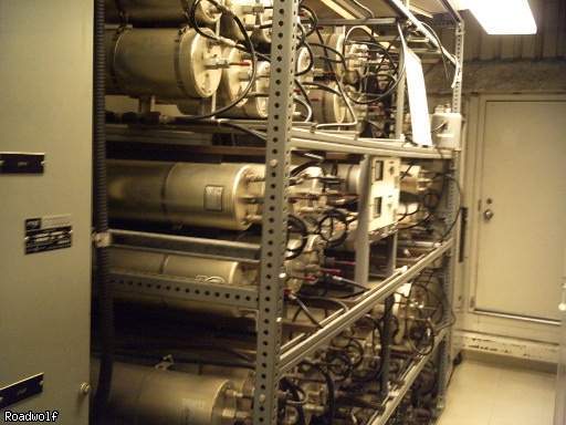
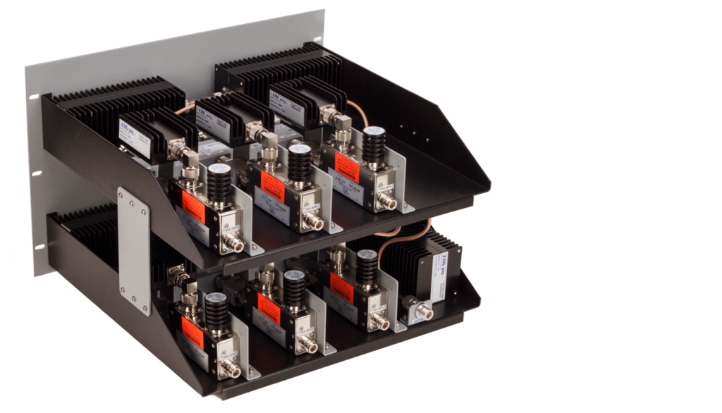
There is only two types of combiner systems…Cavity Combiners and Hybrid Combiners.
Their are benefits and down sides to each type, I will cover those here shortly.
Combiner systems can get extremely complicated, but tonight’s discussion will be broken down to it’s simplest form so everyone has a clear understanding to how a basic combiner system works, whether Transmit or Receive type is used, without getting into the complicated math and system configurations.
An example of the one of the considerations for the needed bandwith of a system as its being designed is below
P_{dBm}=\frac{10 \times {log_{10}(kT)}_{dBm}}{Hz}+NF_{dB}+(10\times log_{10}(B)_{dB})+{CNR}_{dBm}\\P_{dBm}=\frac{-174_{dBm}}{Hz} + 7 + (10 \times log_{10}((22 \times 10^6)_{Hz}) + 0.5861\\P_{dBm}=-92.989673 \equiv -93
The “Master” or receive only antennas were mounted at the top of the 110′ tower to place the receive antenna as far away vertically from any of the transmit antennas located at the base of the tower, basically at 15′ above ground level.
The transmit antennas were mounted on a horizontal ladder type structure about 36″ apart from one another. Total of 21 transmit antennas.
This provided the maximum level of protection from transmitter influence. Using this setup, each repeater no longer had to have a duplexer costing over a $1000, reducing the cost of each repeater installation and the biggest benefit was each repeater receiver had the same high quality receive signal.
System layout of the above system, providing receive RF to 32 repeater receivers only.
Transmitters were not combined on this system.
This is a modern day 20 channel Cavity combiner system with RF power monitoring capabilities.
Space limitations plays a big part of which system is going to be used at some repeater sites.
Cavity costs are also a factor.
This Hybrid setup can accommodate 6 transmit channels. You would need to duplicate each “Module” for the number of transmitters involved. Each shelf has three “Modules” set for a specific frequency.
This setup can add additional frequencies easier than the cavity type, however the the signal losses are considerably higher and are normally addressed depending on the performance level that the system needs to reach.
