TEK NET 20220911
The Henderson Amateur Radio Club is pleased to present our Tek Net every Sunday evening, starting at 8pm local time (0300 UTC).
The audio portion of the Tek Net will be found on the Henderson Amateur Radio Club Repeater Network (RF). The audio may also be accessed via Echolink (W7HEN-R node 740644) and Allstar (node 44045).
The audio will refer to this page, so that the listener can more fully understand the concepts as they are presented.
All are welcome!
September 11, 2022
“How to use your multi-meter, whether its a digital or Analog meter type”
I have been asked many times over the years “What test equipment should I get to use on my ham radio gear?”
That question is as loaded as the “What kind of girl friend or wife should I look for dad?
Fortunately, the answer is much easier and a lot less confusing when choosing a multi-meter.
In my opinion, the first piece of test equipment you should get is a good multi-meter. You want to be able to measure volts, both AC & DC.
You will need to be able to measure current to see if a circuit is operating correctly or not.
Measuring resistance will let you check components and wiring to see if they are open or shorts.
I’m not going to try to take you thru a first year Electronics Technology class, but you can see how a multi-meter will serve you trouble shooting circuits, checking parts or even running down problems in your automobile’s electrical system and around your house’s electrical system.
In 1920, a British Post Office Telegraph engineer, Donald Macadie, is credited with inventing the very first multimeter. The story goes that he was frustrated that he needed to carry a bunch of different tools when working on telecom lines, so he created one tool that could measure amperes, volts, and ohms. Leading to the product being named the AVOmeter. Whats interesting is that 40 years later when I got my Simpson 260 meter, it had many of the same ranges that Macadie’s meter had.
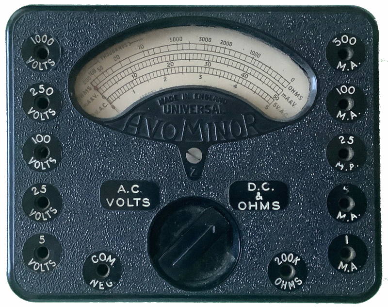
In the 1960’s my first VOM was a Simpson 260 multi-meter. This was real work horse when it came to fixing radios. The main drawback was it was constructed in a Bakelite housing, which meant after the first drop on to the sidewalk meant you would have to glue it back together. Seldom saw mine or any technicians meter that didn’t have the scars of service life.
Now digital multi-meters are cheaper and more accurate than the analog versions and aren’t as suseptible to damage when dropped like the D’ Arsonval meter movement of analog meters.
This meter is a Harbor Freight meter and cost about $4.95 and is given away free during some sales promotions.

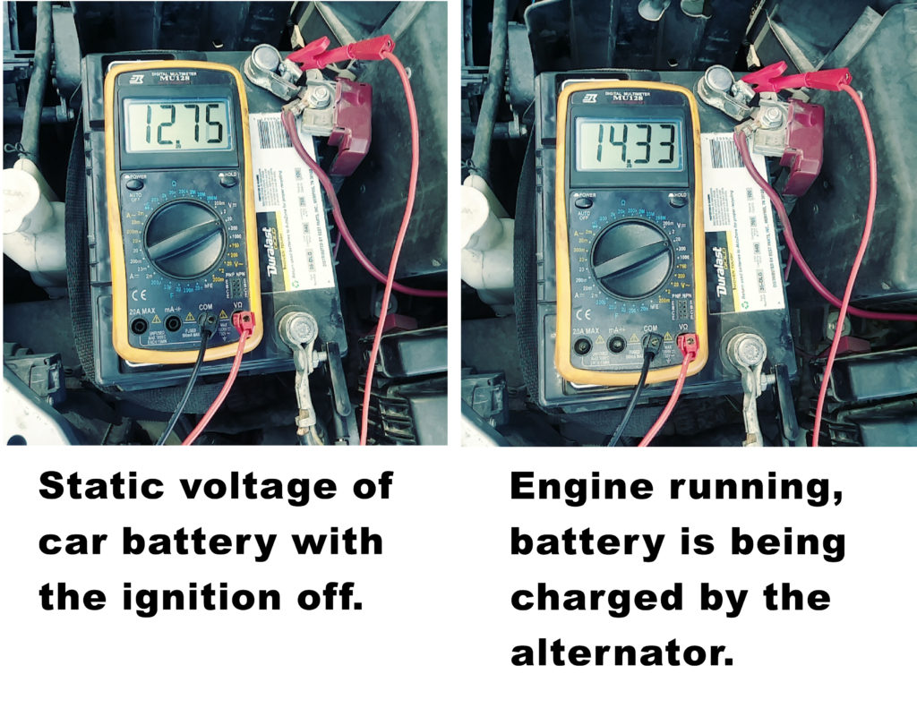
Let’s start with checking your vehicle’s electrical system….There are times when my car was slow to crank over, checking the battery voltage was good, further investigation found that the battery clamps were corroded and loose. Cleaning and tightening solved the problem.
To the right you can see the condition of your battery and that the alternator is working correctly, charging the battery.
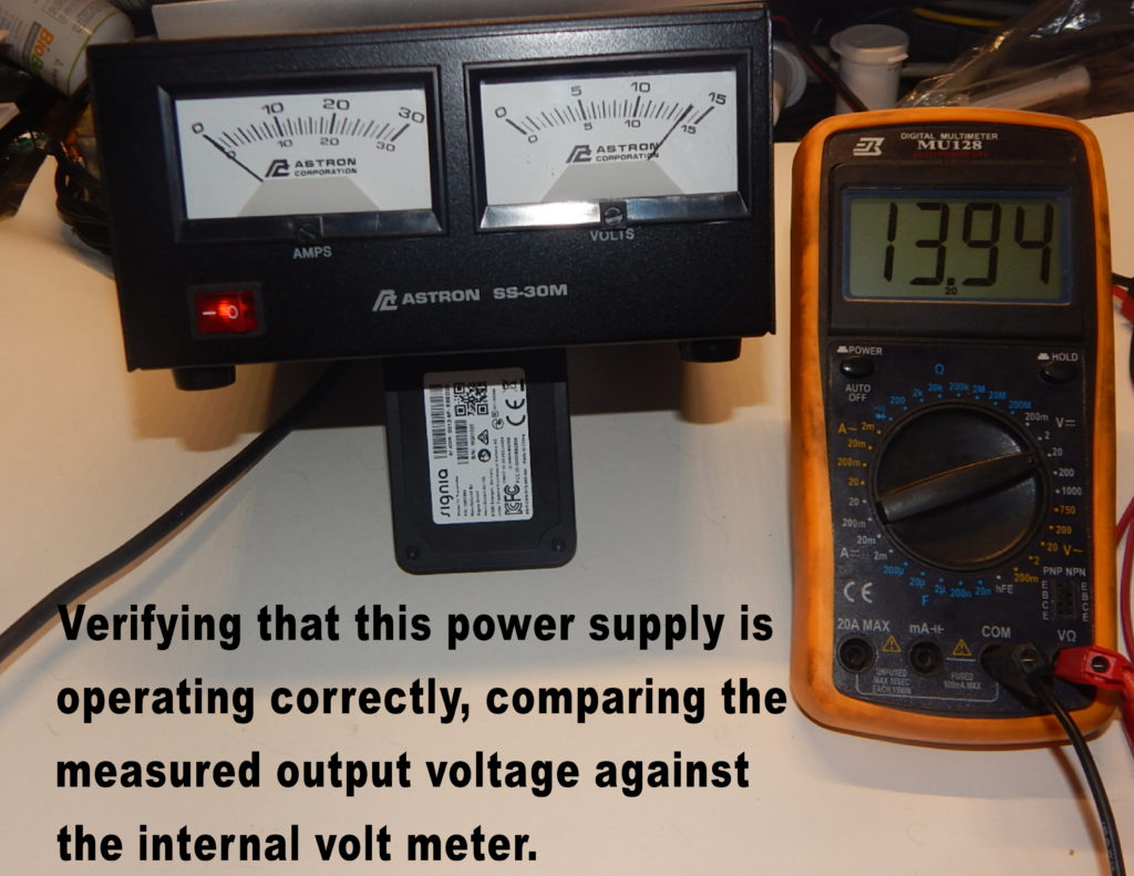
Here we’re checking the output of my power supply to see if it is close to the meters on the front.This indicates that the power supply is providing +13.9 volts. By connecting my two-way radio and transmitting a signal I can verify if my power supply is supplying the radio with enough current during transmit. A 100 watt radio will draw about 20amps of current if the power supply is capable of 20 amps or more.
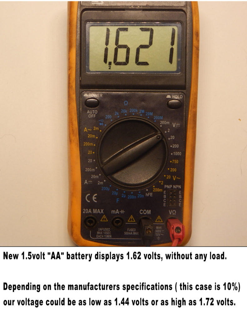
How about checking alkaline or rechargeable batteries.You should always know what the percentage of accuracy is for your meter. It will be in the owners manual or sheet for each scale and range so your measurements are more accurately displayed.
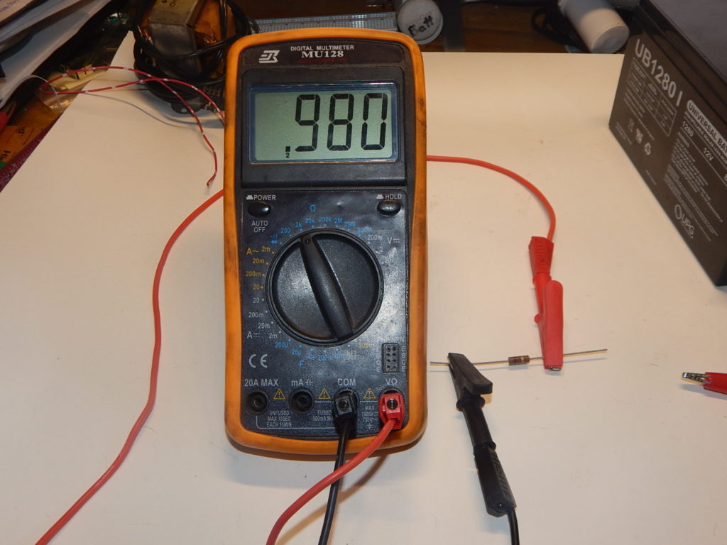
Checking parts now days is a must if you are building a kit or need a specific value resistor. My eye over the years are not as sharp as they use to be, but the ohm meter function saves the day. Here is a 1000 ohm resistor. Definietly within the tolerance for this resistor.
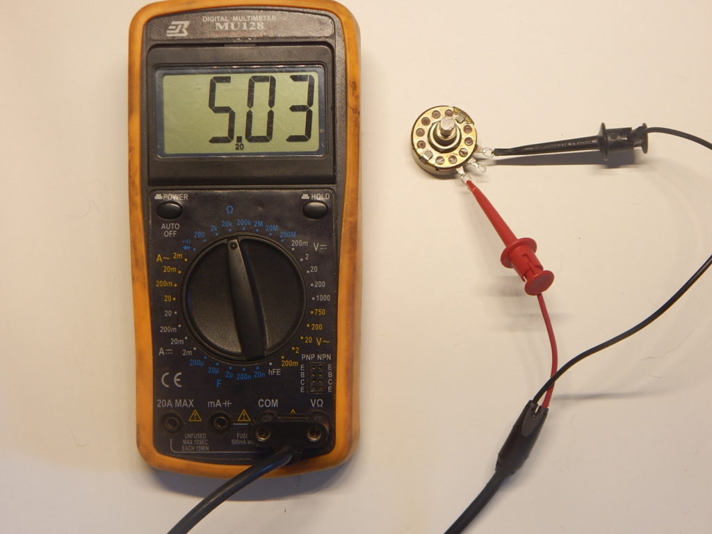
Ever have a component that isn’t marked or has some strange nomenclature stamped on it. Here we are checking a potentiometer and it confirms that it is a 5K potentiometer.
This is also a good way to check for an intermittent or bad ON/OFF switch section on a volume control potentiometer.
By shorting the leads together while in the ohms function, it should read zero or a few tenths of an ohm.
Remember this ohmic reading if you are going to check some circuit wiring for shorts or open. Checking the center conductor on your coax to an antenna when you have placed a 50 load at the far end (antenna end) you will see the 50 ohm plus any loss in the coax which is normally very minimum.

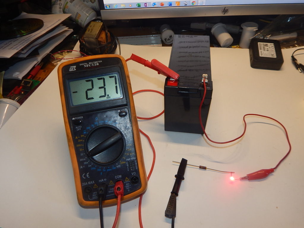
Here you are seeing two functions of the meter. The meter is series with the led and current limiting resistor that’s attached to the battery. The measured current with this resistor is drawing 23.7 Ma, which is correct for this 25Ma LED.
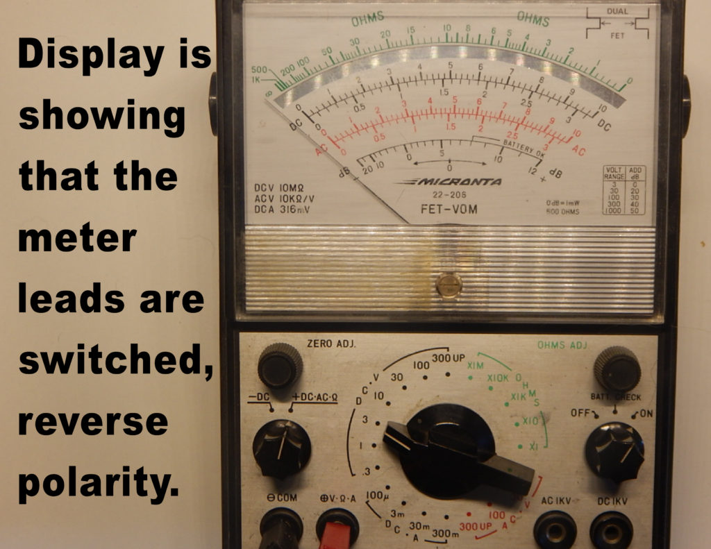
Notice the negative sign on the display, this is showing that the meter leads are reversed. When measuring a DC voltage with digital meter if the leads are reversed it will show the negative sign, that’s because the display follows the RED or positive connection to the meter.
If using an analog meter, you will have to be diligent in the use of the Positive and Negative leads while making a voltage or current measurement.
Its pretty quick and obvious that the leads are reversed or if the Black lead is on ground and you get this condition, not to worry…you have the leads plugged into the meter wrong. Some meters like the one to the right had a lead switch so you could swap the leads to the meter without unplugging the leads.
