BUILDING A REGENERATIVE RECEIVER

By Robert johnson N7FLR

After interviewing Robert and getting a bunch of photos of his project receiver, I found that now I think a kit like this would be a fun project for those who cant decide on their next project.

I’m sure Robert will be happy to answer your questions and we all want to hear your comments.


The schematic of the Armstrong one tube regenerative receiver kit that I purchased from the Borden Radio Company. This was a very reasonably priced kit.

This kit is named in honor of Edwin Howard Armstrong who invented the regenerative receiver in 1912 while he was an electrical engineering student at Columbia University.

As a historical note: Edwin Armstrong is also generally credited with inventing the oscillating transmitter (although Lee de Forest won in the United States Supreme Court the patent litigation over who was the inventor of the oscillating transmitter); the super regenerative receiver; the super heterodyne receiver; and FM radio (although Armstrong lost a patent dispute over the invention of FM radio). My only comment about this is that litigation in the courts does not guarantee that justice will prevail; it merely provides an opportunity for justice to prevail.

The completed receiver:

To the left we see an illustration of the antenna connections.

One connection is for a long wire antenna and one connection is for a short antenna.

The capacitor C1 serves as an antenna coupler between the long antenna to coils L3 and L2 .  Coils L3 , L2 and variable capacitor C2 form a tuneable tank circuit.

The tank circuit is resonant when the sum of the inductances of the coils L3 and L2 is equal to the capacitance of C2 . 

The resonant tank circuit passes the magnetic energy of a collapsing magnetic field around the coils L3 and L2 over to the plates of the variable capacitor where it is stored in the form of an electrical charge.

When the electrical charge on the plates collapses, the electrical energy passes back to the coils to form the magnetic field around the coils again.

(The tank circuit can also be called an LC circuit) The resonant frequency of the tank circuit will be the RF frequency that the radio is tuned to on the variable capacitor


. This kit makes the radio tuneable to the RF frequencies in the AM broadcast band.

The radio frequency in the tank circuit builds up quite a bit of voltage as the current is passed back and forth between coils L3 and L2 and the variable capacitor C2.

This build up of energy is what leads the LC circuit to be called a tank circuit because it stores quite a bit of energy. It has been compared to the stored kinetic energy in a flywheel.

The energy in an LC or tank circuit stores enough voltage to push 0.1 volts through a germanium diode or 0.6 volts through a silicon diode to provide a necessary minimum forward bias across the diode detector in a crystal radio.

The coil, L1, is called the “tickler coil” and is what makes the radio a regenerative receiver.

The RF passes from the tank circuit through capacitor C3 to pin 3 of the tube to the control grid of the tube.

The control grid has a minimal negative bias (a small negative charge) that comes through the resistor R2.

Resistor R2 has a significant resistance of 2.2 megaohms so we can see that the negative bias on the control grid is quite small.

The filament (pins 1 and 7 of the tube) serves as a heater that boils off electrons when the filament gets hot. 

When the control grid is sufficiently positively charged by the positively charged half of the RF signal coming from the antenna to overcome the small negative charge on the control grid, the negative electrons emitted from the filament (heater) are attracted towards and through the screen of the control grid.

The electrons then are attracted toward and through the positively charged screen grid (pin 4 on the tube) and then on and through the negatively charged suppressor grid to land with considerable force onto the surface of the positively charged plate. (plate is pin 6 of the tube).

The electrons land on the positively charged plate with such force that some of the electrons bounce off the plate.

However, those electrons that bounce off the plate are repelled back to the plate by the negatively charged suppression grid.

**Note that the negatively charged suppression grid is between the positively charged screen grid and positively charged plate. The negatively charged suppression grid isn’t connected to a pin on the tube, but is connected internally inside the tube to the filament.

The negative charge to the suppression grid is small because the filament is charged with only 3 volts from the A battery of the receiver.

When the RF signal to the control grid is in the negative portion of its cycle no electrons are attracted to the now negatively charged control grid. Subsequently no electrons are attracted to or through the positively charged screen grid or to the positively charged plate.

Thus the control grid serves as a rectifier (detector) similarly to the Fleming valve, invented by John Fleming in Britain.

A diode or crystal detector (rectifier) as used in a crystal radio to rectify the RF signal is no longer needed.

Later, Lee de Forest improved upon the Fleming valve by inventing the audion tube. The audion tube added more current to the control grid which enabled it to not only serve as a detector (rectifier), but also as an amplifier of the RF current.

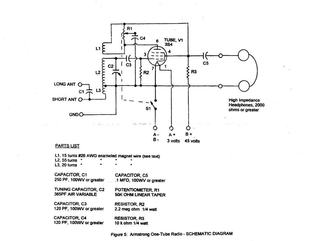
The regeneration takes place when the RF current is detected and amplified by the control grid and goes through the positively charged screen grid and plate and through a potentiometer (R1) and then through the tickler coil (L1).

The tickler coil, L1, induces its RF current back into the antenna coils (L3 and L2) where the RF is sent back through C3, to the control grid, the screen grid, the plate and the tickler coil all over again.

This process occurs over and over; each time amplifying the RF signal over the amount of the original RF signal that comes down from the antenna.

For example, if the LC circuit is tuned to 540 kilocycles, the regenerated current will pass through the tickler amplification cycle 540,000 times per second.

This includes the amplification of the modulated AM messaging embedded on the RF signal. The amplified signal passes from the screen grid at pin 4 through the capacitor (C5) and on to the ear phone.

The C5 capacitor serves to block any direct current from coming through to the earphone.

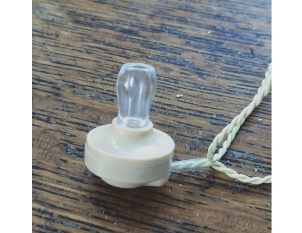
The earphone must be a high impedance earphone to match the high impedance of the receiver.

(This radio uses high voltage to enable its screen grid and plate to attract electrons from the control grid to the screen grid and to the plate. The high voltage in the tube results in the high impedance to the ear phone in this radio.)

As you can see above, the soldering is not crowded and not too critical.


The high voltage needed for this receiver is developed by five 9-volt batteries snapped together, leaving the (+) positive and the (-) negative terminals ready to be connected to the fahnestock clips.

The 3-volt battery is supplied by two “D” cells


Here is the high impedance crystal ear phone that comes with the kit.

A high impedance transformer could be also used to drive an audio amplier with a speaker.

I hope this gives some understanding of the Armstrong one tube regenerative receiver.

There are many alternative ways to make a regenerative receiver.

I saw a schematic (one of six) that Edwin Armstrong submitted with his patent application for the regenerative receiver back in 1914.

It doesn’t look anything at all like the schematic to the regenerative receiver discussed here.


Below is another 1-tube regenerative receiver that uses plug-n coils to give you a tuning range of below 500Khz up to 30Mhz.

We’ll talk about that next time. . .

73 and look forward to next week’s Tek Net!

DE WB6AMT Earl