May 15, 2022

Directional Antenna Creation
By Tony Dinkel WB6MIE

Directional Beam antennas …

As ham radio operators we have read about them … used them … built them or at the very least, knew a ham that had them.


Hams use a lot of different kinds of antennas, ground planes, dipoles, discones, G5RVs, just to name a few. But imagine living in a time when you couldn’t just head down to Gigaparts to buy the antenna that you need.

This is the paper written in 1926 by the creators of the “Yagi Uda Array” or “beam” antenna, as we know it today.

https://www.wa5vjb.com/references/Yagi1926.pdf

This is a contemporary design of a commercially available 3 element yagi for the 430 to 450 mhz UHF band.  The 3 elements refer to the fact that there are three rods employed in this antenna design, not counting the horizontal element, commonly referred to as the boom.

Only one rod is driven with RF as a dipole and it is referred to as the “Driven Element”. The driven element is the only active antenna in a Yagi Uda array.

The other elements, the reflector and the director(s) are referred to as parasitic elements.

Note the difference in lengths between the elements. The reflector is slightly longer than the half wave driven element and the director is slightly shorter than the driven element.

The reason for this difference is that phase shift is required to make a yagi antenna directive. This phase shift is accomplished by making the reflecting element slightly inductive or electrically longer causing a lag in the induced current. By making the director element slightly capacitive or electrically shorter, that causes a lead in the induced current. This directs the wave front down Mr. Yagi’s wave canal.

Back to the original paper … 

Suppose that a vertical antenna is sending out electromagnetic waves in all directions around it. If a straight metallic rod of finite length could be vertically erected within the field of its propagation, then the behavior of this metal rod would be as follows:

When the length of this rod is equal to or slightly longer than a half wavelength, the current induced in it will be in phase with or lagging behind the EMF caused by the electric wave, and the rod will act as a “wave reflector.”

On the other hand, if the length is made somewhat less than a half wavelength, the current induced in it would be leading before the EMF and the rod would act as a “wave director.”

A single wave reflector placed behind a radiating antenna is sufficient to cause directive radiation of the radio wave. It is especially efficient when placed a quarter wavelength behind the radiating antenna. Again a wave director placed in front of and more than a quarter wavelength distant from the radiating antenna is also effective in producing a directive radio wave.

When several wave director rods are arranged along a line with intervals equal to or more than a quarter wavelength, the wave energy will be projected chiefly along this line and the series of these wave directors forms what the authors will call a “wave duct” or “wave canal”.


According to the researchers’ experience, a parabolic reflector is not necessary for producing a beam of radio waves.

However, according to my experience, that’s not what I found in the early 70s when I built a point-to-point link system on 1299mhz.


Due to the wavelength, Yagis proved too small and fragile for the outside environment on the hilltops I was linking between.

High winds, ice and snow were common for most of the winter.

So a 1 meter (39 inch) parabolic reflector with a rigid 2 element yagi feed antenna was the best choice.

This particular 2 element antenna is called a “splash plate” feeder due to the large cross section presented to the forward radiating wave front.

As much energy as possible is directed back into the dish so it can be focused and radiated in the desired direction. The result is a mechanical design for a point-to-point antenna that is survivable in harsh weather conditions.

This antenna lasted almost 30 years and only failed because the entire mounting structure blew off the front of the building in a severe windstorm, taking all of the antennas with it. To this day it rests somewhere in the bottom of Blackstar Canyon in eastern Orange County California.

It would probably still work if I pounded the dents out of it.


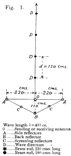
Getting back to Yagi and Uda … a wave reflector rod is placed a quarter wave behind the antenna, B, and two more wave reflectors, A – A, one being on the left and one being on the right side are placed a half wave distant from the antenna. See Figure 1 to the right:

These three rods form a tri-antennary reflecting system, which will hereafter be called a “trigonal reflector”. Frankly, it looks a lot like an approximation of a corner reflector to me in this particular configuration, but I will stick with the author’s description.

Two more reflector rods C and C are shown in Figure 1 to the right. These are not as efficient as reflectors A and B, but their existence enables closer screening of waves in the backward direction.

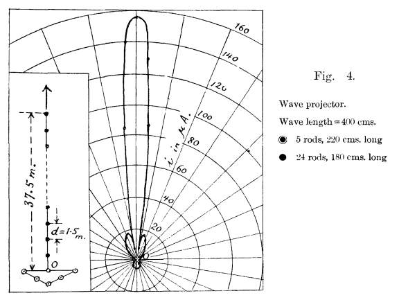
When this reflector system is employed in a receiving station, they are especially effective in eliminating external disturbances from behind.

Today, we refer to this as “front to back ratio” in relation to the forward gain, expressed in db.

Figure 1
(Yagi & Uda, 1926, p 50)

Combined with these screening rods, the trigonal reflector is now formed of 5 rods. The position of the screening rods are nearly midway between A and B, and a slight variation in their position is practically ineffectual.

When the trigonal reflector is employed in a receiving station, it may better be called a “trigonal collector.” These days we call it a receive antenna.

Now the projection of the sharpest beam ever produced of electric waves can be effected by the combination of a trigonal reflector and a wave duct. This combination will be called a “wave projector”.

Thankfully, the “trigonal reflector” assembly on the back of the yagi uda array did not seem to catch on over the years. The single reflector rod B is all that is required for efficient directivity.

The directivity can be improved by increasing the number of directing rods contained in the wave duct. As an extreme case, when the sending and the receiving stations are connected with a line of wave canal, the transmission of wave energy can be the most efficaciously accomplished.

Some typical results of observations with short electric waves are shown here.

Here we see the plan view of the arrangement of conductors for the wave length of 4.4 meters.

I asked Siri what frequency has a wavelength of 4.4 meters and she said that it is about 68 mhz.

In Figure 2 is shown the directive effect of a trigonal reflector with five rods. No wave director is here employed, and the intensity is measured with a receiving system comprising a crystal detector and a galvanometer.

Figure 2
(Yagi & Uda, 1926, p 50)

Remember, in 1926 you couldn’t just go to Giga parts or order a BaoFeng from Amazon to test your antenna.

In Figures 2, 3 and 4, the radius vector of the polar diagram gives the measure of intensity in the receiving system placed in that direction, the distance from the sending station being kept constant.

Figure 3
(Yagi & Uda, 1926, p. 51)
Figure 4
(Yagi & Uda, 1926, p 51)

Now if the wave duct or wave canal is provided, the directivity becomes remarkably augmented.

In the case of Figure 3, 19 rods of 180 centimeters length (a quarter wave being equal to 110 centimeters) were arranged along a line with an interval of 150 centimeters.

In the case of Figure 4, 25 rods of 180 centimeters were set up with an interval of 150 centimeters. The length of the reflector rods was made equal to the exact half wavelength of 200 centimeters.

The field measurements were made under the same conditions, and the short wave generator was also kept at exactly the same conditions for all of the observations in Figures 2, 3 and 4.

It is easy to explain how the radiation in the side direction becomes minimum, and the polar diagrams prove the realization of the sharpest beam ever produced of electric waves … at least in 1926.

Many various cases have been made in the Tohoku Imperial University, Sendai, and further details will in time be published in the Journal of the Institute of Electrical Engineers of Japan.

Many of these referenced publications are now available on the internet by searching Yagi, Uda or yagi antenna.


Some additional information from K7JTC Licensing Class …

According to several accounts, Shintaro Uda developed the antenna and Hidetsugu Yagi (who was his student) developed it further.

Yagi spoke English (Uda did not) and was able to present the ideas at English speaking functions, so much so, that the antenna eventually became know by his name.  Eventually, Yagi managed to get a Japanese Patent.  Later that patent was transferred to the United Kingdom.  

Yagi frequently gave Uda credit for the initial design, while claiming the enhancements as his own.

The original Yagi/Uda paper from 1926 was sourced from Kent Britain’s website at www.wa5vjb.com.

The paper can be accessed directly at https://www.wa5vjb.com/references/Yagi1926.pdf

Used without permission as I assumed that the material is in the public domain due to its age and is available at many public websites.

Any other pictures or text contained in this presentation are my own work and no rights are implied, retained, or reserved.

Tony Dinkel WB6MIE

References:

Yagi, H., & Uda, S. (January 9, 1926). Projector of the Sharpest Beam of Electric Waves. Proceedings of the Institute of Electrical Engineering, Tohoku Imperial Academy Sendai  2.(2), 49-52. 

(downloaded from https://www.jstage.jst.go.jp/article/pjab1912/2/2/2_2_49/_pdf)

(also available from https://www.wa5vjb.com/references/Yagi1926.pdf)