May 8, 2022

Build an FM Deviation Monitor & why we need one.

First off… Obviously I don’t claim that this project is meant to replace a professional FM Frequency Deviation Monitor.

One aspect of radio transmitters that has always plagued operators is having a good sounding signal whether it is the modulation of an AM transmitter or the deviation of an FM transmitter.

Amateur radio FM transmitters should be modulated or “Deviated” to a full 4.5 -5 khz level to sound rich and full of audio characteristics of the operator’s spoken voice.

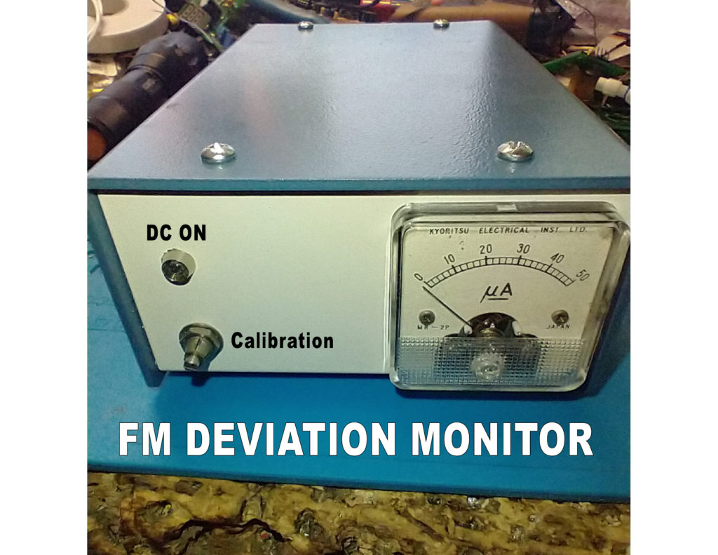
When listening to the repeaters I’m sure you have heard stations that you have to turn up the volume to hear what they are saying, then the next voice is extremely loud. The disturbing thing I find about this condition, is the stations going back to these operators are  telling them that they sound fine into the repeater, and in the same sentence ask to repeat their last?

That’s ridiculous, be honest and be critical about how you are hearing them, then they will then know they have a problem and need to address it to correct the issue.

Your transmit audio is THE SINGLE MOST IMPORTANT characteristic of your signal. Yes…your antenna is important, yes… having enough RF power is important, BUT if you can’t be understood or heard…what’s the point?

Here is why it is important…if a station is only deviating their transmitter to a level of say 2.5 Khz (narrow band) deviation and is using an HT to talk to the repeater AND has a lot of path noise on his signal at about 2Khz in level…..when he talks, he will not be heard….PERIOD!

BUT….if the station is fully deviating a 4.5-5 khz signal his voice will rise above the noise level and be totally intelligible, even though his signal is still noisey to the repeater! AMAZING!

.

This project was originally built and used in 1978 when I wanted to monitor my 2-Meter transmitter’s deviation but I didn’t have an FM service monitor at my disposal.

The layout in this chassis isn’t crowded and wiring is not complicated.

Shown is the meter, battery packs for the +9Vdc, the SA-818 on a carrier board, the power supply regulator board ( behind the batteries), and the meter rectifier circuit board.

On the rear of the box is an On/Off switch, a BNC antenna connector and a BNC for our oscilloscope connection.

On the front of the box is the power LED indicator and a Calibration potentiometer next to the meter.

See below under “Project Parts” for what you will need to build this project.


At the time using a tube receiver I was able to see my audio signal with a scope monitoring the discriminator output of the receiver. We can’t do that with most of today’s digital receivers.

One of the problems to overcome was getting a consistent audio level out of the receiver. That’s not a problem using the SA-818 with its 8 step audio output level.


Using the SA-818 module programmed to 146.520Mhz, I added a BNC connector connected to the receiver’s audio output.

The waveform can be seen on my oscilloscope’s display.

This audio signal is an AC signal so by adding a rectifier circuit, now we have a DC signal that can drive a DC meter (a 50ua meter movement).


Calibrating the unit:


Using a service monitor’s generator output and feeding an on-frequency signal of 146.520Mhz with a 1000hz tone being deviated at 5Khz, I will get a set audio level out of the SA-818.

With this consistent audio level fron the 818, the rectifier board of 4 diodes will drive the meter to full scale easily.

Now adjusting the calibration potentiometer, the meter’s needle is adjusted down to the full scale point printed on the meter face.

See below photo.


The amount of DC voltage that is being created with the audio output of the SA-818 set to Level 8, there will be plenty of DC voltage so that just about any meter movement from 50ua (shown) to several Milliamps can be used for this project.

Using the calibration control, adjust the needle to the “50” and that is now our 5Khz point peak deviation point.

While transmitting, the received audio signals can then be viewed and compared to our 5Khz full scale deflection point. Normal deflection will probably be about “30” or higher.

To check for my peak deviation a simple “Test 1..2..3..4 with a heavy emphasize on the four gives me a good solid “40-50” on the meter.


After building this device, here is a way for a station to be able to tell if their transmitter needs to be adjusted for full deviation ( programming analog vs digital ), possibly change to a different microphone or change the way you talk into your microphone to get your voice peaks as high and close to 5Khz deviation as possible.

How to talk into your microphone was covered in a previous Tek Net and is a whole different discussion.


“Project Parts”

A small piece of prototyping circuit board material is used for the power supply and the meter diode board

The meter diode board consists of four silicon diodes wired as a bridge rectifier, you can also use a 4-lead rectifier module also.


There is no critical wiring in building this unit. Everything is low impedance, making shielded wiring unnecessary except for the RF coax to connect the SA-818 board to the antenna connector.

If you care about the way your signal is received by others and want to see what your signal looks like, then this project will fill the bill.

Good luck building this project and contact me as I can assist with most of the parts and circuit board material and the carrier board for the SA-818.

You can obtain the SA-818 from NiceRF.com, the Battery packs are an Amazon item, I have a few of the small ua meters and the chassis you choose is up to you.

73

WB6AMT Earl