Tek Net
March 12, 2023
“A short course in understanding what VSWR is and how it effects your transmitted signal”

VSWR stands for Voltage Standing Wave Ratio. This term came into existence back in the day when Telegraph lines were being serviced or troubleshot by field repairmen, attempting to repair and locate damaged (shorted or open) telegraph lines in the field.
There is many pieces of equipment available to measure VSWR on your antenna system.
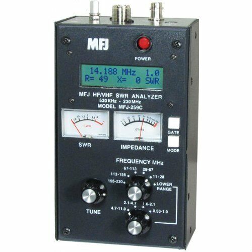
The unit to the right is a MFJ-259C this unit is frequency specific and must be set to the frequency that is being used for this test. Simply connect your antenna to this unit and measure.
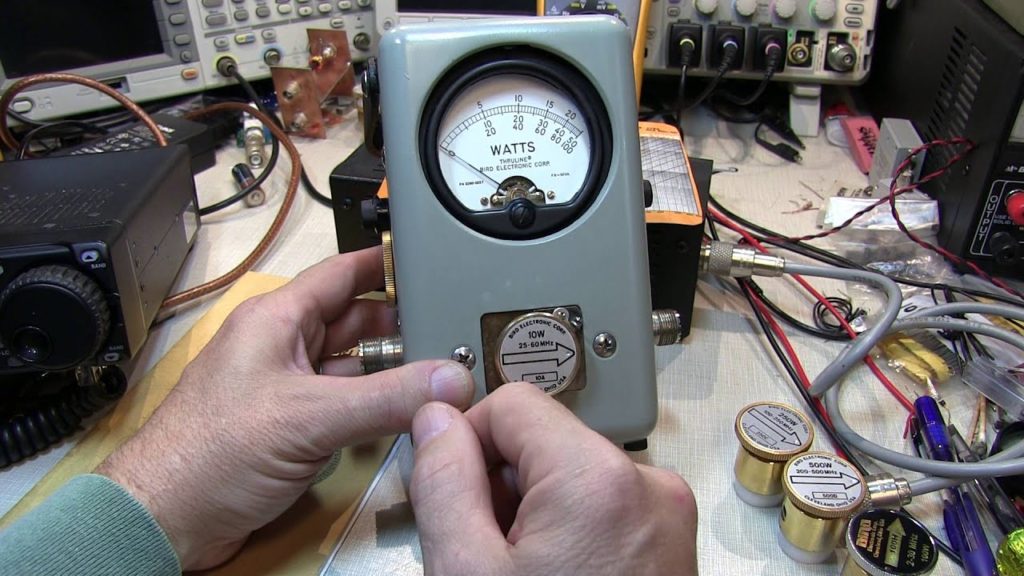
The unit below is a BIRD Model 43 Directional Wattmeter that goes inline between the transmitter and the antenna.
This uses a “Slug”, the part with an ARROW that is rotated in each direction, have a frequency range and Maximum RF level that will be displayed on the meter.
By simple turning the slug in the direction that the arrow is pointing, allows you to measure the amount of RF energy flowing in that direction when the transmitter is on the air.
![]()
By using this watt meter or any other inline wattmeter you will have to use a formula ( see below) to use the Forward and Reverse readings to calculate that actual VSWR.
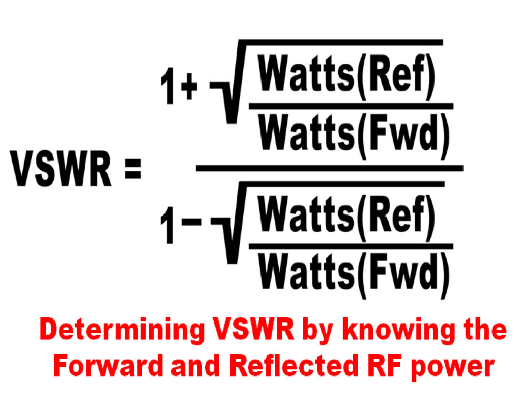
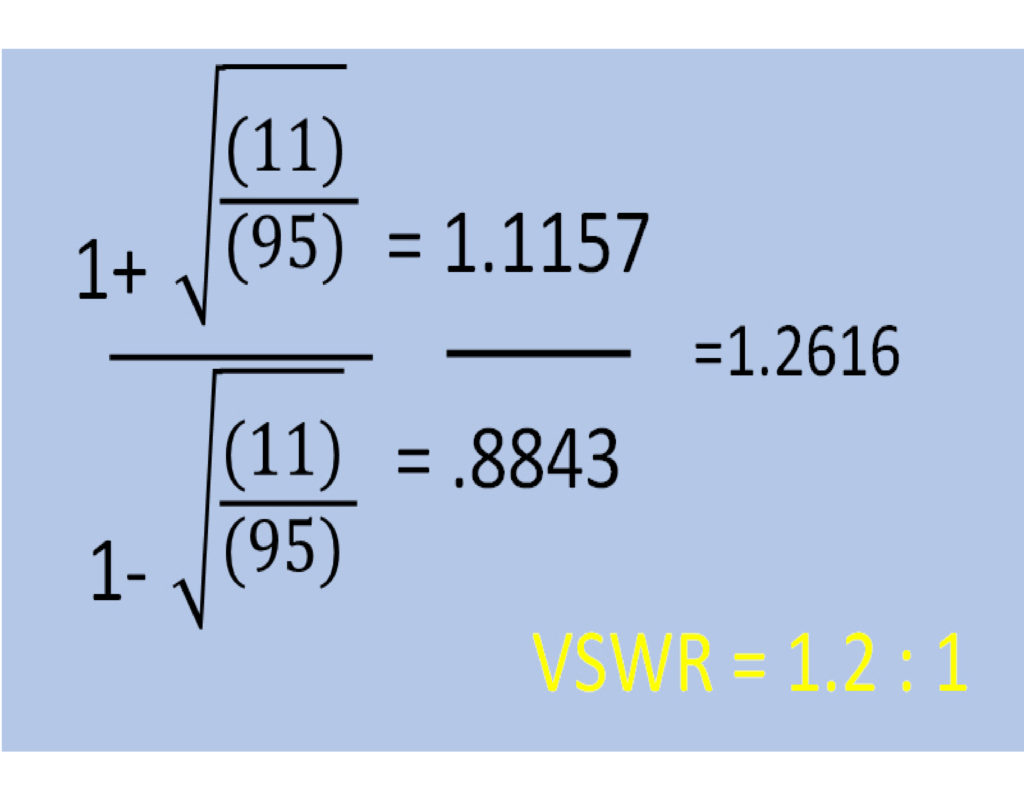
This example is from my 100 watt UHF mobile, having 95 watts measured forward and 11 watts reflected.
Whether you use a calculator or the calculator app on your cell phone, they all seem to have the square root function available.
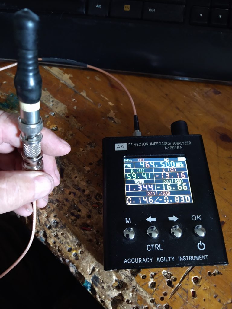
This small hand held VNA ( Vector Network Analyzer, is compact and a favorite among hams not wanting to spend a lot of money on test equipment.
These units are available from about $30 on up.
As seen on the display, several parameters about the antenna system is shown besides just the VSWR.
Here we can see that the antenna is resonant on 464.500 Mhz with a VSWR of 1.344:1, very acceptable for a hand held radio’s antenna.
The use of a short quality jumper cable will not affect a antenna’s measurement.
It needs to be mentioned that longer lengths and the quality of coax used for the feedline can be detrimental to getting an accurate VSWR reading on an antenna like a base or repeater station antenna.
FYI…at no time should you ever use a VNA or antenna analyzer like the MFJ unit above, at a repeater location or in an environment where there is RF energy in the area, this will lead to extremely inaccurate readings and can damage the sensitive circuitry of the VNA.
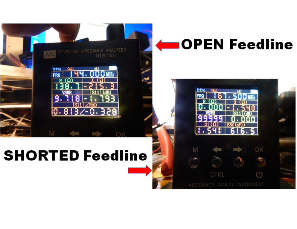
Here we can see how a VNA can assist with displaying a shorted coax feedline or an open coax feedline.
By displaying the “R” or ohmic resistance of the feedline, it’s easy to see if the coax is open (138.7 ohms) or shorted ( 0 ohms)
Below you can see how the VSWR actually affects your amount of RF energy at the antenna.
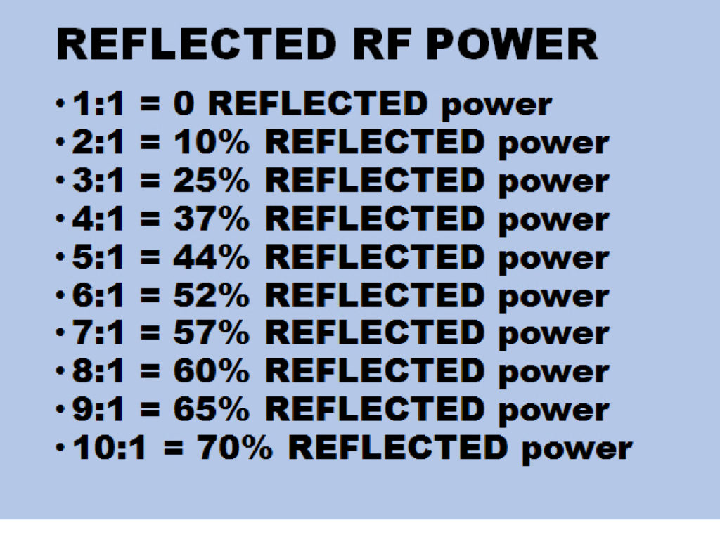
The amount of reflected energy is important because of how it can affect the transmitter’s amplifier stage or external amplifier if your using a linear amplifier between the transmitter and the antenna.
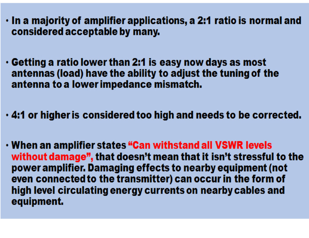
Keep in mind that any reflected energy on the antenna system is going to be fed back into the transmitter’s amplifier stage.
When this happens there are conditions that will create higher voltages at times now twice the original operating voltage of the circuit design.
As with all radio components, they have a designed voltage range for each part.
Exceeding this voltage can lead to component failure as well as excessive high temperatures being generated by the components affecting nearby parts, again leading to stage failures.
There are ways that equipment can deal with VSWR.
![]()
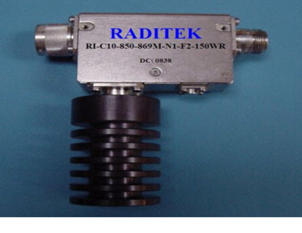
To the right is a typical Circulator that is used at repeater sites.
Because of the amount of RF energy present at some radio sites the external dummy load may have to be increased to handle the amount of energy that is flowing down the feedline. Shown is a 25 watt load.
(Story time)
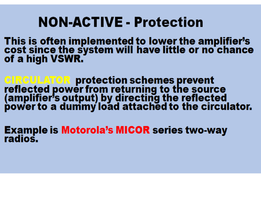
A Circulator is often placed on the output of a repeater to protect the transmitter’s output due to the continuous duty cycle while it is on the air.
In this application the circulator directs the reflected energy to a separate dummy load.(shown above)
RF energy at repeater sites can often times be very high and will be fed back down nearby antennas into nearby transmitters.
The circulator feeds this energy into the dummy load helping to prevent RF energy from entering the final transmitter’s stage and creating signal mixes ( IMD – Intermodulation Distortion) that can then be sent out the feedline and re-radiated, causing interference on receivers operating on these newly created signals.
![]()
As you’ve seen here, VSWR is present on all antenna systems and can be easily measured.
Correcting a high VSWR condition may not be as easy to fix though…but that’s going to be a another TEK NET session.
If you need assistance to check your system, there many hams with VNA’s or watt meters that will be willing to show you how to do it and help with measuring your system’s VSWR.
![]()
